输入输出可控的液压系统蓄能器设计(含CAD零件图装配图,CATIA三维图)(任务书,开题报告,外文翻译,论文说明书19000字,CAD图7张,CATIA三维图)
摘要
随着科学技术和工业进程的发展,液压技术越来越广泛的应用于机械工程领域。作为液压系统中重要的辅助储能元件,蓄能器也得到了广泛应用。在现代社会中液压系统对蓄能器的性能要求越来越高,通过对蓄能器进行结构改进和功能完善研究,可以进一步的提高液压系统的经济性、环保性和可靠性等等。
本文针对实现蓄能器输入输出可控的功能这一问题,进行了相关研究,通过将传统蓄能器与其他液压元件组合的方法,控制蓄能器内气体容积和压力,从而实现了输入阶段蓄能能力可调、输出阶段压力可控的功能。本文主要进行了以下研究工作并得到了如下结论:
(1)在传统蓄能器工作原理以及国内外相关研究成果的基础上,采用改变蓄能器气体容积的思路来实现蓄能器输入输出可控的功能。
(2)根据研究思路及相关流体液压知识,完成了对输入输出可控的蓄能整体装置完成了回路设计,以及装置中相关液压元件的选择。根据蓄能器的相关使用条件,对蓄能器的性能参数设计计算以及工作压力的选择原则方面进行了简单叙述。
(3)针对蓄能器性能研究,建立了蓄能器的数学模型,得到影响其性能的相关参数因素,并对增压缸的活塞杆组进行受力分析得到相关基本方程,进一步的对蓄能器能量密度进行基本方程建立,得到了影响其工作效率的参数因素。
(4)针对蓄能器的工作过程,在AMESim软件平台上对整体蓄能装置进行了模型搭建,尺寸初定以及仿真分析。通过仿真得到了蓄能器在进液和放液过程中,蓄能器内压力、蓄能器内液压油质量、活塞组位移变化曲线,进一步对蓄能器的工作过程进行了研究。
(5)针对相关参数对蓄能器的性能影响,基于AMESim仿真平台,通过改变蓄能器预充气压力、预设恒压值及活塞面积比,对比仿真得到了一系列蓄能器内压力等相关参数的变化曲线,进一步得到了参数对蓄能器性能影响的结果。
关键词:蓄能器;可控;恒压输出;AMESim仿真实验
Abstract
With the development of science and technology and industrial processes, hydraulic technology is increasingly used in the field of mechanical engineering. As an important auxiliary energy storage component in hydraulic systems, accumulators are also widely used. In modern society, the hydraulic system has higher and higher requirements on the performance of the accumulator. By studying the structural improvement and function of the accumulator, the economical, environmentally friendly and reliable hydraulic system can be further improved.
In this paper, the related research is carried out on the problem of realizing the controllable function of the input and output of the accumulator. By combining the traditional accumulator with other hydraulic components, the volume and pressure of the gas in the accumulator are controlled, thus realizing the input stage. The function of adjustable energy storage capacity and controllable pressure in the output stage. This paper mainly carried out the following research work and got the following conclusions:
(1) Based on the working principle of traditional accumulators and related research results at home and abroad, the idea of changing the volume of accumulator gas is adopted to realize the controllable function of accumulator input and output.
(2) According to the research ideas and related fluid hydraulics knowledge, the complete circuit design of the energy storage integrated device with input and output control is completed, and the selection of relevant hydraulic components in the device is completed. According to the relevant operating conditions of the accumulator, the design and calculation of the performance parameters of the accumulator and the selection principle of the working pressure are briefly described.
(3) For the performance study of accumulator, the mathematical model of accumulator is established, and the relevant parameter factors affecting its performance are obtained. The basic equations are obtained for the force analysis of the piston rod set of the booster cylinder. The basic equations are established for the energy density of the energy, and the parameter factors affecting the working efficiency are obtained.
(4) For the working process of the accumulator, the whole energy storage device was modeled, dimensioned and simulated on the AMESim software platform. Through the simulation, the pressure of the accumulator, the quality of the hydraulic oil in the accumulator and the displacement curve of the piston group during the process of liquid inlet and discharge were obtained. The working process of the accumulator was further studied.
(5) Based on the influence of relevant parameters on the performance of the accumulator, based on the AMESim simulation platform, a series of accumulator pressures are obtained by comparing the accumulator pre-inflation pressure, the preset constant pressure value and the piston area ratio. The variation curve of the relevant parameters further obtains the result of the influence of the parameters on the performance of the accumulator.
Key words:accumulator; input and output controllable; constant voltage output; AMESim simulation experiment
目录
摘要 III
Abstract IV
第一章绪论 1
1.1引言 1
1.2蓄能器的功用 1
1.3蓄能器的类型 1
1.4蓄能器的历史及研究现状 2
1.5主要研究内容及采用的技术方案及措施 3
第二章输入输出可控蓄能器设计 5
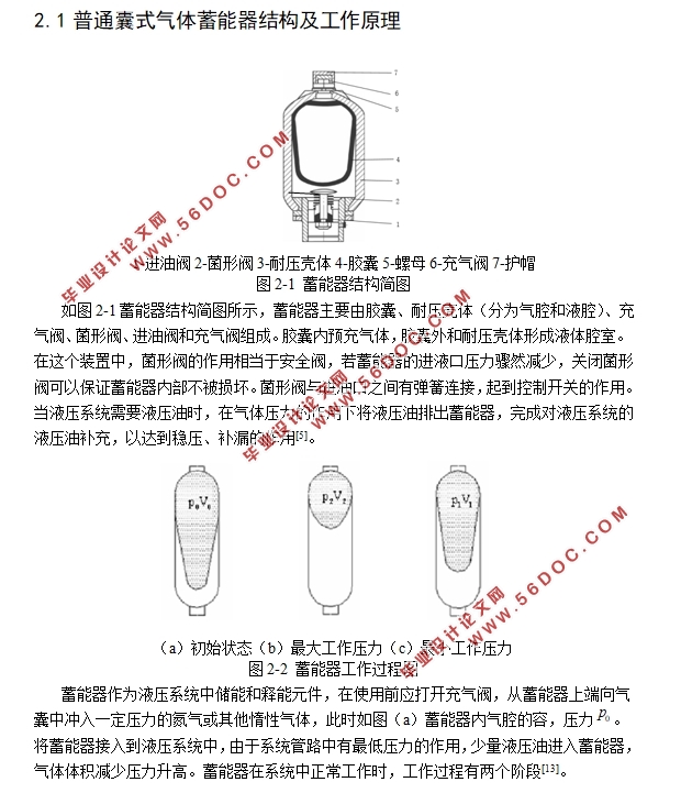
2.1普通囊式气体蓄能器结构及工作原理 5
2.2输入输出可控式蓄能器结构及工作原理 6
2.3输入输出可控式蓄能器功用 7
2.4蓄能器应用设计计算 8
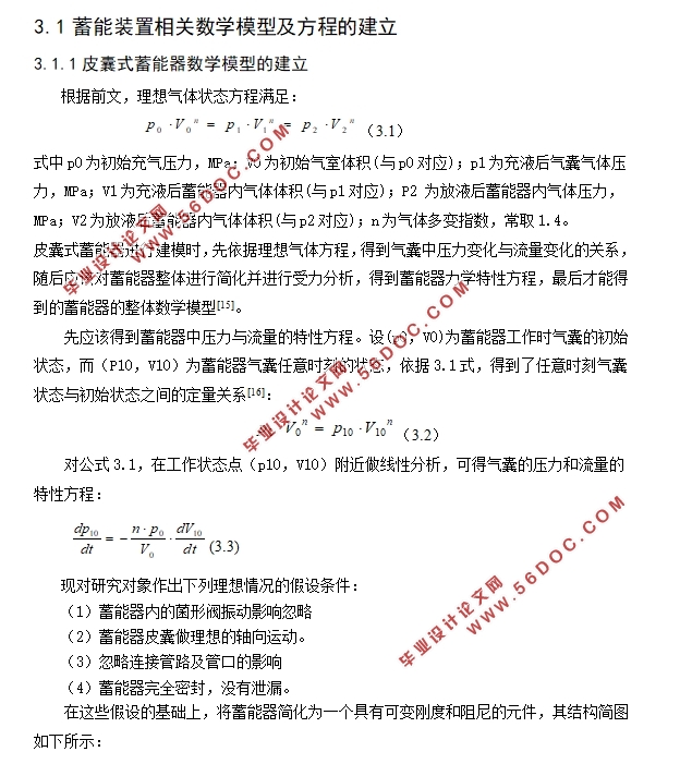
2.4.1蓄能器工作过程 8
2.4.2蓄能器总容积及有效工作容积计算 9
2.4.3蓄能器充气压力及工作压力的选取 11
2.5输入输出可控式蓄能器性能参数计算 11
2.6本章小结 13
第三章蓄能器数学模型及仿真模型的建立 14
3.1蓄能装置相关数学模型及方程的建立 14
3.1.1皮囊式蓄能器数学模型的建立 14
3.1.2气液增压缸基本方程 16
3.1.3 蓄能器储能密度方程 17
3.2AMESim介绍 20
3.2.1AMESim液压基本元素建模法 20
3.2.2液压基本元件介绍 21
3.3AMESim建模 22
3.3.1蓄能器部件建模 22
3.3.2气液增压缸建模 23
3.3.3蓄能装置总体建模 23
3.4本章小结 24
第四章液压系统工作过程仿真分析 25
4.1蓄能装置工作过程仿真结果 25
4.1.1引言 25
4.1.2进液阶段蓄能能力可调仿真 26
4.1.3放液阶段输出可控仿真 26
4.2关键元件参数对蓄能装置的性能影响 28
4.2.1 蓄能器充气压力对蓄能装置的性能影响 29
4.2.2 增压缸活塞面积比对蓄能装置的性能影响 30
4.2.3不同的压力预设值对蓄能装置的性能影响 31
4.3蓄能装置在液压系统中的仿真 32
4.3.1进液阶段吸收液压冲击仿真 32
4.3.2放液阶段作动力源回路仿真 34
4.4本章小结 37
第五章总结与展望 38
参考文献 40
|