40T桥式起重机小车运行机构的设计(英文版)(含CAD图,SolidWorks三维图)(任务书,开题报告,外文翻译,文献摘要,论文说明书英文版9000字,CAD图8张,SolidWorks三维图)
Abstract
With the rapid development of modern society, with the continuous development of social economy in our country and the continuous development of scientific research, today's market competition has become more fierce, and cranes have become more widely used due to advanced automation technology and technological advances. The scale is also more ambitious. As a result, crane production companies all hope to improve production technology and improve production efficiency. The manufacturing industry also has higher requirements for cranes and more comprehensive performance.
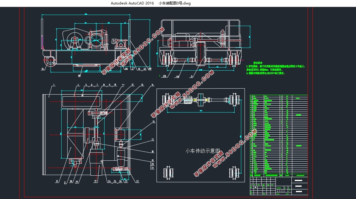
This design is about the trolley running mechanism of the bridge crane. The so-called lifting trolley is a vehicle that runs along the trolley track and whose hooks perform the vertical lifting movement. Its scope of work is in the field of cuboids formed by driving, and its application in the workshop is extensive. The crane trolley has four running wheels. When arranging the components on it, the center of gravity of the mechanism should be close to the longitudinal centerline of the small frame, which can result in a uniform wheel pressure.
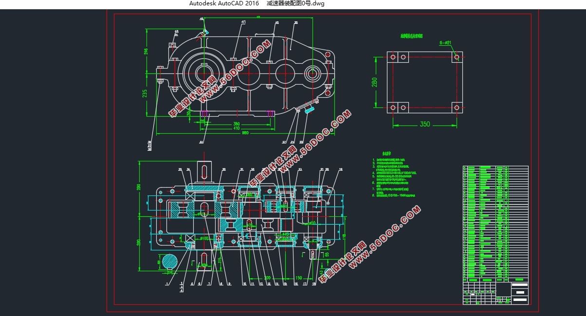
At the very beginning, it is determined that the trolley running mechanism is a transmission scheme with a closed gear transmission. The speed reducer is directly connected with the motor, and the speed reducer is in the middle of the trolley. Secondly, through the overall design calculation of the trolley running mechanism part, and Selection and calculation of axes, brakes, buffers, motors, etc. verification calculations, structural designs and design calculations of parts of the reducer of the operating mechanism, the design of the trolley running mechanism is accomplished through a series of designs to meet the weight requirements up to 40T.
Keywords: lifting trolley, design, reducer, operating mechanism

Contents
Statement of Originality i
Copyright Letter of Authorization to The Dissertation i
Abstract iv
Chapter 1 Introduction 1
1.1 Preface 1
1.2 Research Status at Home and Abroad 1
1.3 Future research directions 2
Chapter 2 Introduction of Bridge Cranes 4
2.1 Composition and Features of Bridge Cranes 4
2.2 Development Trends of Bridge Cranes at Home and Abroad 5
2.3 Bridge crane trolley 6
2.4 Bridge crane trolley operating mechanism 10
Chapter 3 Trolley running mechanism design 11
3.1 Requirements for Designing a Trolley 11
3.2 Trolley running mechanism transmission scheme 13
3.2.1 With open gear transmission scheme 13
3.2.2 Closed gear transmission scheme 14
3.3 Select wheels and tracks and check their strength 17
3.3.1 Choose wheel 17
3.3.2 Intensity Check 17
3.3.3 Calculation of operational resistance 19
3.3.4 Select The Motor 21
3.3.5 check the heating condition of the motor. 22
3.3.6 Selection of speed reducers 22
3.3.7 Validation of operational speed and actual power requirements 23
3.3.9 Checking the power of the reducer according to the starting condition. 25
3.3.10 Checking the starting non-slip condition. 25
3.3.11 select the brake. 27
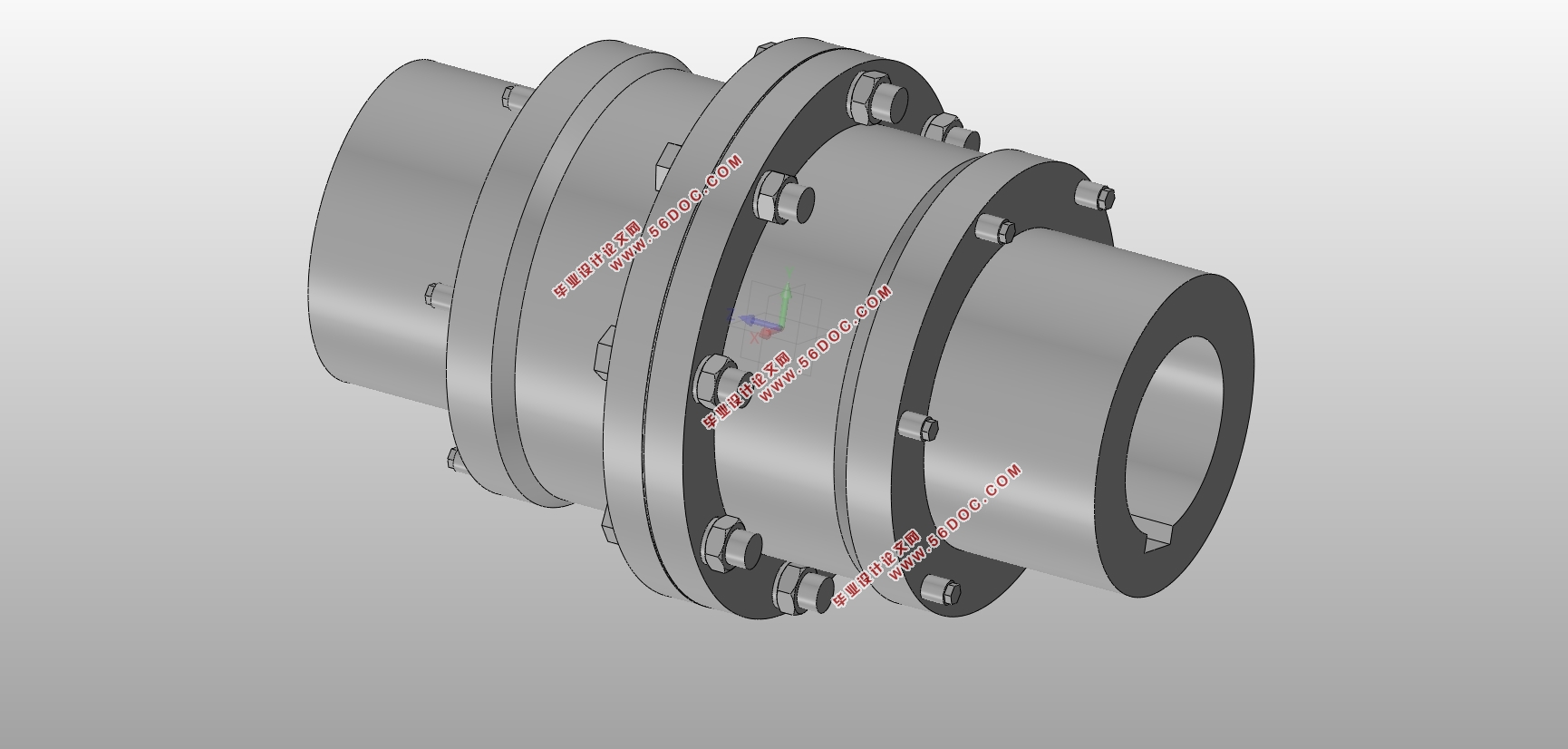
3.3.12 select high-speed shaft coupling and brake wheel. 27
3.3.13 select low speed shaft coupling. 28
3.3.14 Test for low speed floating shaft strength 29
Chapter 4. Selection of trolley frame 31
4.1 To determine the type of trolley frame 31
4.2 To determine the structure of the trolley frame. 31
5.1 Summary 33
5.2 Deficiency 33
References 35
Appendix………………………………………………………………………………………...36
Acknowledgement……………………………………………………………………………….39
|