жїМмЬхялПззЈЛњялФЃЩшМЦ(КЌCADЭМ)(ШЮЮёЪщ,ПЊЬтБЈИц,ЭтЮФЗвы,ТлЮФЫЕУїЪщ12000зж,CADЭМ13еХ)
еЊвЊ
МаОпЙуЗКгІгУгкИїжжжЦдьЙЄађжаЃЌгУвдНЋЙЄМўЖЈЮЛВЂРЮЙЬЕФМаГждквЛЖЈЕФЮЛжУЃЌвдБуАДееВњЦЗЩшМЦЙцЖЈЭъГЩвЊЧѓЕФжЦдьЙ§ГЬЃЌВЂЧвВЛЭЌЕФХњСПШчЕЅМўЁЂГЩХњКЭДѓСПЩњВњЖјЪЙгУКЭПЊЗЂВЛЭЌЕФМаОпЁЃдкЛњаЕМгЙЄжаЃЌаэЖрВњЦЗЕФЙиМќСуМў——ЛњзљЁЂЯфЬхЕШЃЌЭљЭљашвЊНјааОЋУмПзЯЕЕФМгЙЄЁЃетаЉПзЯЕВЛЕЋвЊЧѓПзЕФГпДчКЭаЮзДОЋЖШИпЃЌЖјЧвИїПзМфМАПзгыЦфЫќЛљзМУцжЎМфЕФЯрЛЅЮЛжУОЋЖШвВНЯИпЃЌгУвЛАуЕФАьЗЈМгЙЄКмФбБЃжЄЁЃЮЊДЫЃЌЙЄГЬММЪѕШЫдБЩшМЦСЫИїжжзЈгУялПзМаОпЃКялФЃЃЌДгЖјНтОіСЫПзЯЕЕФМгЙЄЮЪЬтЁЃВЩгУялФЃКѓЃЌялПзОЋЖШЛљБОЩЯПЩВЛЪмЛњДВОЋЖШЕФгАЯьЃЌЖдгкШБЗІИпОЋЖШялПзЛњДВЕФжаЁЂаЁЙЄГЇЃЌОЭПЩвдгУЦеЭЈЛњДВЁЂЖЏСІЭЗвджСЦфЫќОИФзАЕФОЩЛњДВРДХњСПМгЙЄОЋУмПзЯЕЁЃДѓДѓЬсИпСЫЩњВњаЇТЪЁЃ
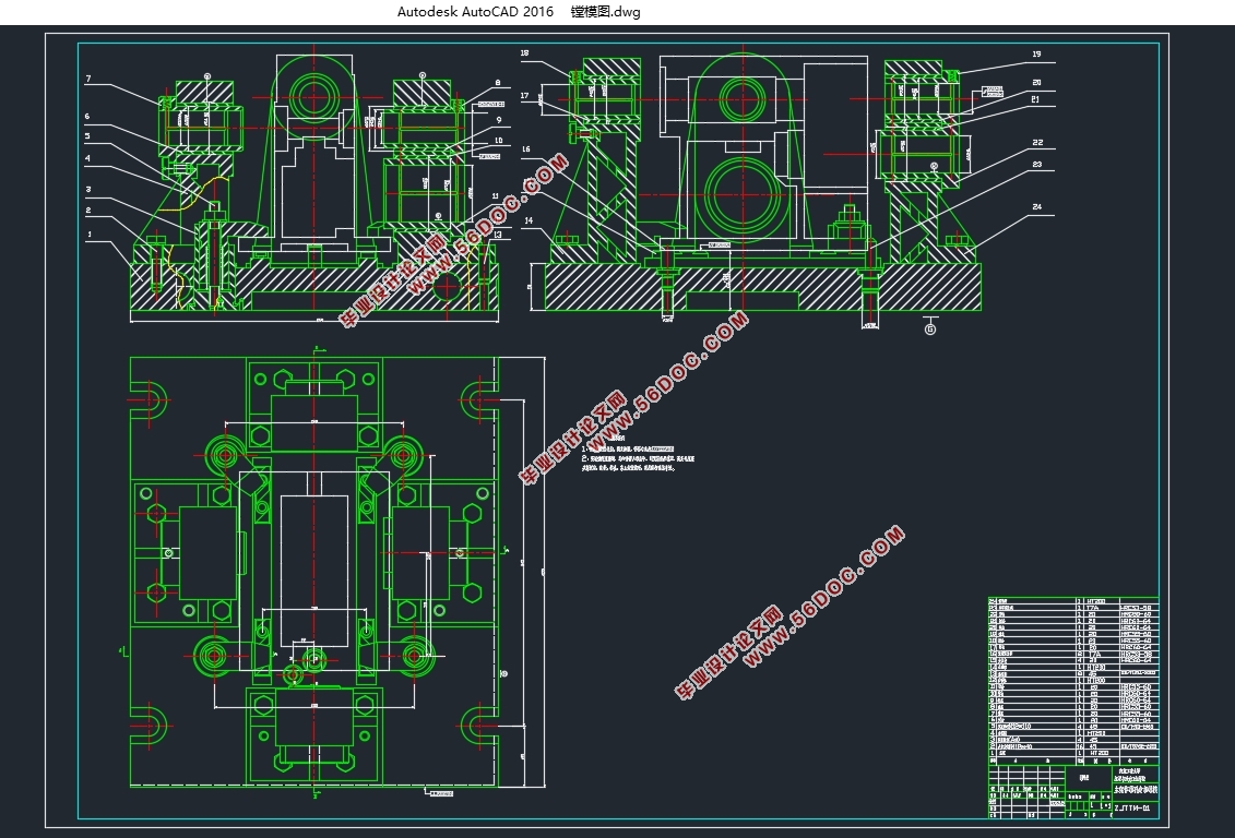
БОДЮЕФЩшМЦШЮЮёЪЧжїМмЬхялПззЈЛњялФЃЩшМЦЁЃТлЮФЪзЯШЖджїМмЬхНјааЗжЮіЃЌШЛКѓПЊЪМЖЈЮЛМаНєЗжЮіЃЌВЂжЦЖЈЫљвЊЕФялПзМгЙЄЙЄвеТЗЯпвдМАЫљвЊМгЙЄПзЕФЪ§ОнЗжЮіЃЌШЛКѓОпЬхНщЩмСЫялФЃЕФЩшМЦЙ§ГЬЃЌжївЊАќРЈялФЃЕФНсЙЙЗНАИЃЌЯрЙиЧаЯїВЮЪ§ЕФМЦЫуЃЌЕЖОпЕФбЁдёЕШЯрЙиЩшМЦЕШЙЄзїЁЃзюКѓНшжњCADШэМўЭъГЩСЫЯрЙиЭМжНЕФЛцжЦЁЃ
ЙиМќДЪЃКялФЃ МгЙЄЙЄве ЧаЯїСІ
Main frame boring machine boring mold design
Abstract
The fixture is widely used in various manufacturing processes, to the workpiece positioning and firmly clamped in place, so that in accordance with the design requirements to complete product manufacturing process requirements, and different quantities such as single, batch and mass production and use and development of different fixture.In mechanical processing, key frame, body parts -- many products, often need to carry on processing precision holes. Size and shape precision of these holes not only require the hole is high, and the precision of position between each hole and the hole and the other datum is also high, with the general approach is very difficult to guarantee.Therefore, engineering design special jig boring: boring mode, thus solving the problem of machining holes. The boring boring precision mold, basically can not be influenced by the accuracy of machine, small factories, for lack of high precision boring machine bed, can use ordinary machine, power head and other modified the old machine to batch processing precision holes.greatly improving the production efficiency.
This design task was boring machine boring jig design of main frame. The paper first carries on the analysis to the main frame body, and then start positioning clamp analysis, analyze and formulate the boring processing routes to and to the processing hole data, and then presents the design process and die structure, mainly including boring mode, calculation of the correlation of cutting parameters, tool selection and other related design etc. work. finally completed the drawing of the relevant drawings using CAD software.
Keywords : Boring jig Processing technology The cutting force
1.1ЩшМЦШЮЮё
жїМмЬхялПззЈЛњялФЃЃЌгУгкзЈЛњялПзМгЙЄЙЄађЃЌЪЧХфЬзялПззЈЛњЪЙгУЕФзЈгУЙЄзАЁЃ
1.2ВФСЯМАЙЄвевЊЧѓ
ВФСЯЃКHT200 гВЖШЃК176ЁЋ241HB
жїжсПзЃК2×ЇЖ ДжВкЖШRaЮЊ0.8
ЮЯИЫПзЃКЇЖ ДжВкЖШRaЮЊ1.6
ЇЖ50 ДжВкЖШRaЮЊ1.6
ЮаТжПзЃКЇЖ ДжВкЖШRaЮЊ1.6
НјИјПзЃКЇЖ ДжВкЖШRaЮЊ1.6
ЇЖ ДжВкЖШRaЮЊ1.6
1.3ЩшМЦвЊЧѓ
1ЃЉБЃжЄФъЩњВњИйСь12000ЬЈ/Фъ
2ЃЉБЃжЄжїжсЯфЬхЕФОЋЖШвЊЧѓ
3ЃЉСІЧѓНсЙЙЩшМЦДяЕНБъзМЛЏЃЌЭЈгУЛЏЁЃ
ФПТМ
еЊвЊ I
Abstract II
ЕквЛеТ аї Тл 3
1.1баОПЕФФПЕФМАвтвх 1
1.2ЙњФкЭтЕФЗЂеЙМАбаОПзДПі 1
1.3БОПЮЬтбаОПЕФФкШн 2
1.3.1баОПФкШн 3
1.3.2баОПвтвх 3
ЕкЖўеТ ЩшМЦШЮЮёЗжЮі 4
1.1ЩшМЦШЮЮё 4
1.2ВФСЯМАЙЄвевЊЧѓ 4
1.3ЩшМЦвЊЧѓ 4
1.4ялФЃЩшМЦЛљБОЙ§ГЬ 4
1.4.2ФтЖЈМаОпЕФНсЙЙЗНАИЃЌЛцжЦНсЙЙВнЭМ 5
1.4.3.ЛцжЦМаОпзмзАХфЭММАСуМўЭМ 5
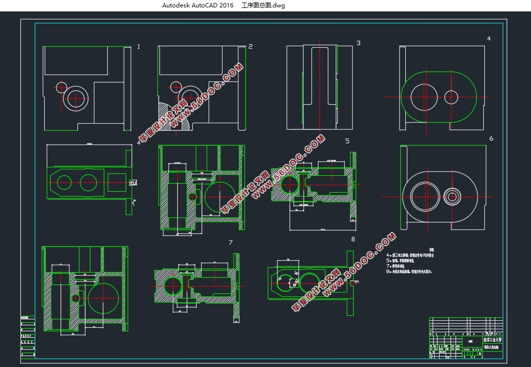
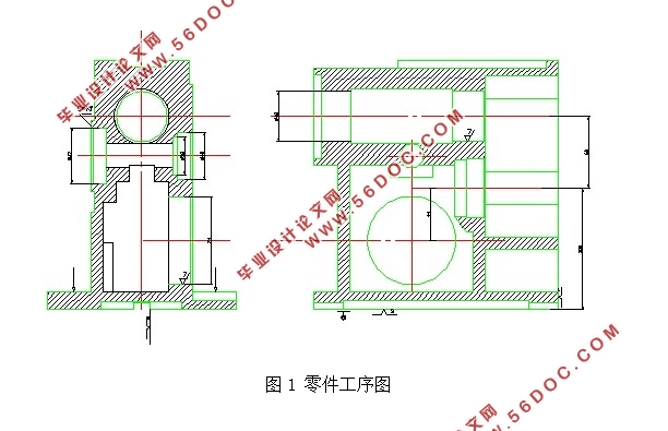
ЕкШ§еТ СуМўЙЄвеЗжЮі 6
3.1ЙЄвеЛљзМЗжЮі 6
3.1.1ЖЈЮЛЗжЮі 6
3.1.2МаНєЮЛжУгыМаНєЕуЕФЗжЮі 7
3.2МгЙЄЙЄвеЗжЮі 9
3.2.1СуМўОЋЖШЗжЮі 9
3.2.2ЙЄвеТЗЯпЗжЮі 11
3.2.3МгЙЄгрСПЗжЮі 12
3.3ЗНАИТлжЄ 14
ЕкЫФеТ ялФЃНсЙЙЩшМЦ 16
4.1ЛцжЦялФЃНсЙЙМђЭМ 16
4.2ялФЃЕФЛљБОзщГЩгыЩшМЦ 18
4.2.1ялЬзЕФЩшМЦ 18
4.2.2ЕЖОпбЁдё 19
4.2.3ялФЃЕФжЇМмНсЙЙ 20
4.3ЖЈЮЛМАМаНєдЊМўЕФЩшМЦ 23
4.3.1ЖЈЮЛдЊМў 23
4.3.2 МаНєЛњЙЙЩшМЦ 24
4.4ЧаЯїгУСПЕФШЗЖЈ 25
4.5МаНєСІЕФМЦЫу 26
4.6ЮѓВюЗжЮі 27
4.6.1ЖЈЮЛЮѓВю 27
Нсгя 30
ВЮПМЮФЯз 31
жТаЛ 33
|