液压缓冲缸设计(含CAD零件图装配图)(任务书,开题报告,论文说明书11000字,CAD图5张)
摘 要
近些年来,海上风力发电已成为世界上发展最快的绿色能源技术。然而,在海上风电设备吊装的过程中,由于风电设备自身重量太大,加上海风、波浪等因素的影响,风电设备会对安装平台造成巨大的冲击,从而使安装过程显得异常困难。这就需要一套缓冲设备,来实现风电设备吊装过程中的承接缓冲。
本文主要研究液压缓冲缸的设计,通过学习和研究、收集有关资料,设计一种用于海上风电设备吊装的液压缓冲缸,实现吊装过程中的承接缓冲。通过该设计,掌握缓冲油缸的设计原理和方法,熟练掌握相关设计软件的使用方法和设计资料的运用。
缓冲类的产品多种多样,本文主要研究的对象是多孔式液压缓冲缸,其缓冲原理是通过设计在油缸壁上的一系列特殊排列的阻尼小孔来实现缓冲。其特点是结构紧凑,使用方便,且吸收能量大。
本文的特色在于通过合理的分析,提出一种对多孔式液压缓冲缸的设计方法。
关键字:海上风力风电;风电设备;液压缓冲缸;缓冲原理
Abstract
In recent years, the offshore wind power has become the world's fastest growing green energy technology. However, in the process of offshore wind power equipment hoisting, its weight is too big, due to the wind power equipment and the factors of wind, wave, wind power equipment can cause huge impact to the installation platform, so as to make the installation process is extremely difficult. This requires a buffer device, to achieve the receiving buffer in the process of wind power equipment hoisting.
This paper mainly studies the design of the hydraulic buffer cylinder, through learning and research, collect the relevant information, design a kind of used for offshore wind power equipment hoisting hydraulic buffer cylinder, to achieve the receiving buffer in the process of hoisting. Through the design, master the design principle and method of buffer cylinder, skilled in the use of the related design software and the use of design data.
Buffer class variety of products, the main research object of this article is multi-orifice hydraulic buffer cylinder, the buffer principle is through the design of a series of special arrangement in the cylinder wall damping holes to realize buffer. It is characterized by compact structure, easy to use, and high power-absorbing ability.
Characteristics of this paper is that through the reasonable analysis, puts forward a design method of multi-orifice hydraulic buffer cylinder.
Key Words: Offshore wind power; Wind power equipment; Hydraulic buffer cylinder; Principle of the buffer
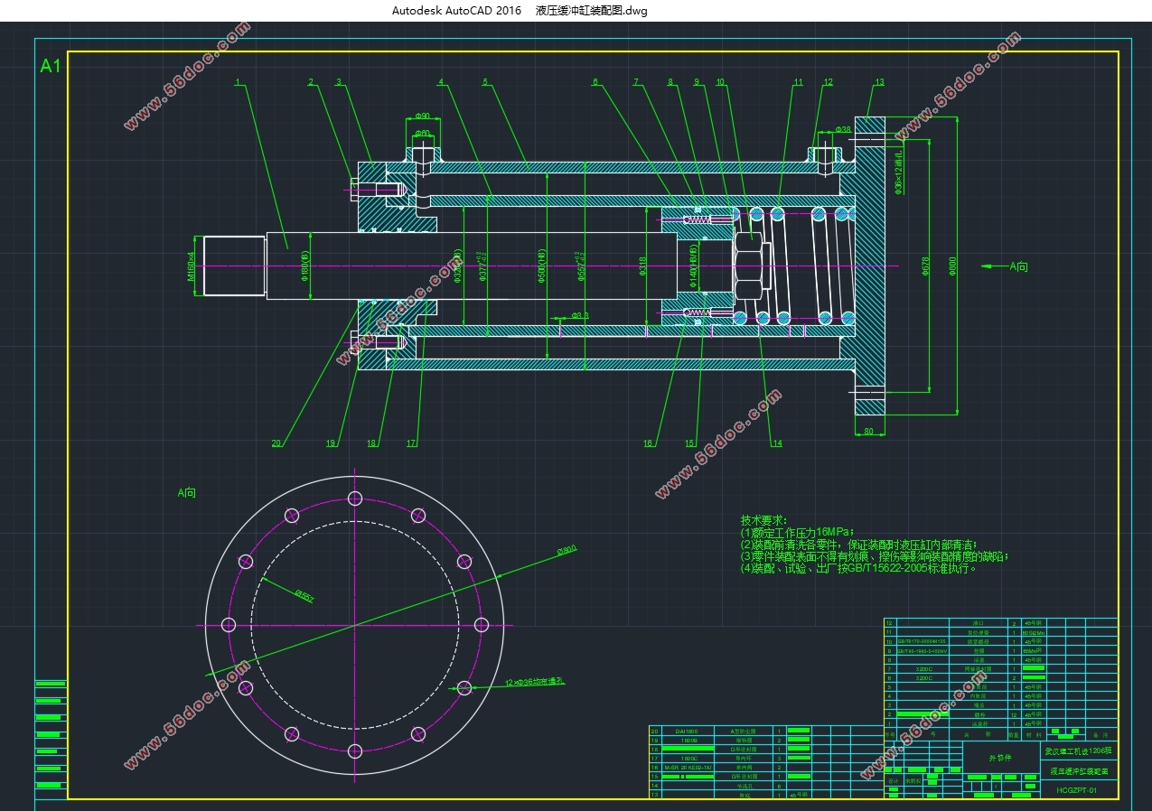
3.1 设计参数
本次设计的相关参数如下:
① 缓冲缸最大冲击负载:800KN;
② 缓冲缸行程:500~1000mm;
③ 缓冲缸直径:320~500mm;
④ 要求保证所吊装的风电设备下降加速度≤0.25g(重力加速度g=9.8m/s2);
⑤ 风电设备的冲击初速度为1.8m/s。

目 录
摘 要 Ⅰ
Abstract Ⅱ
第1章 绪论 1
1.1 海上风电设备吊装过程分析 1
1.2 缓冲器的分类 1
1.3 液压缸的缓冲类型 3
1.4 多孔式渐变节流液压缓冲缸的工作原理及过程 4
第2章 液压缓冲缸的受力分析与能量关系 6
2.1 分析假设 6
2.2 受力分析与能量关系 6
第3章 液压缓冲缸主要尺寸的设计及计算 8
3.1 设计参数 8
3.2 液压缓冲缸安装方式的确定 8
3.3 液压缓冲缸缓冲行程的确定 8
3.4 总缓冲力的计算 9
3.5 液压缓冲缸内缸筒的设计及计算 9
3.5.1 对缸筒的要求 9
3.5.2 缸筒材料的选择 9
3.5.3 内缸筒内径的计算 9
3.6 内缸筒壁厚的计算及验算 10
3.6.1 内缸筒壁厚的计算 10
3.6.2 内缸筒壁厚的验算 10
3.7 节流小孔的设计和布置 11
3.7.1 节流孔数目和孔直径的设计 12
3.7.2 节流孔坐标位置的设计 12
第4章 液压缓冲缸活塞及活塞杆的设计 13
4.1 液压缓冲缸活塞的设计 13
4.1.1 活塞的结构与密封圈的选择 13
4.1.2 活塞支承环的选择 14
4.2 活塞杆与活塞的连接方式 16
4.3 液压缓冲缸活塞杆的设计 16
4.3.1 活塞杆的结构 16
4.3.2 活塞杆的材料和技术要求 16
4.3.3 活塞杆端部结构形式 16
4.3.4 活塞杆直径的计算 17
4.4 活塞杆的导向、密封和防尘 17
4.4.1 活塞杆的导向 18
4.4.2 活塞杆的密封 18
4.4.3 活塞杆的防尘 20
4.5 活塞杆的校核 21
4.5.1 活塞杆强度验算 21
4.5.2 活塞杆稳定性验算 21
第5章 端盖与外缸筒的设计 23
5.1 端盖与缸筒连接形式的设计 23
5.2 液压缓冲缸外缸筒的设计及计算 23
5.3 缸筒底部厚度的计算 24
5.4 连接螺栓的设计与选择 25
5.5 端盖法兰厚度的计算 25
5.6 复位弹簧的选择 26
第6章 液压缓冲缸的油口及排气装置的设计 28
6.1 缓冲缸油口的设计 28
6.2 缓冲缸排气装置的设计 28
6.3 经济性分析 29
第7章 总结与展望 31
7.1 总结 31
7.2 展望 31
参考文献 33
致 谢 34
|