纤维物料旋埋机设计(含CAD零件图装配图)(任务书,开题报告,外文翻译,设计说明书9000字,CAD图纸15张)
摘要
本课题是纤维物料旋埋机的设计,首先应该查阅国内外相关的文献了解当前处理秸秆生物质的各种方法和手段,由于近年低碳化环保,节约能源的意识深入人心,各国在秸秆处理上都有一定的发展,目前的秸秆还田机械主要有旋耕机、秸秆打捆机、开沟机,但是各有一定缺点,本机综合各机结构特点、性能有点,进行设计。
本机需完成三个秸秆处理动作:收集、粉碎、掩埋,三个功能分别有三个装置实现。捡拾器的设计来源于秸秆打捆机的捡拾装置,联合收割机的捡拾器结构复杂且无法牵引,捡拾器的转速有一定限制,每分钟1~2圈,故采用了链传动,而且因为结构的问题水平布置的链轮无法满足要求,因此采用垂直方向的布置,另外考虑到链条的垂度问题,小链轮与大链轮在水平方向有50mm的间距。粉碎装置的动力传动采用带传动,主要因为刀轴的转速达到1000r以上,且设计了两个转动方向相反的刀轴,已达到良好的粉碎效果,设计主动刀轴通过齿轮传动将动力传至从动刀轴,而农业机械所用齿轮精度通常8级精度,而8级的直齿轮线速度无法满足要求,提高精度将增加很多成本,采用斜齿轮相对合理。因为粉碎刀片的厚度较小,如果在刀轴上开长键槽限制刀片的周向移动会降低轴的强度,将轴加工成方轴。
关键词:秸秆粉碎 捡拾器 秸秆还田 秸秆深埋
Design of fiber material rotary burying machine
ABSTRACT
This topic is the design of the fiber material rotary embedding machine, various methods and means should first consult the relevant literature at home and abroad to understand the current treatment of straw biomass, in recent years due to low carbon environmental protection, people's awareness of energy conservation, all countries have a certain development in the straw, straw is now mainly a straw strapping machine, ditching machine, but there are some shortcomings, this machine the machine structure, performance, design.
Mainly divided into three parts: the straw pickup device, straw crushing device, straw burying device. The pick-up device design source pickup in straw baler, pickup structure is complex and not traction combined harvester, picking up the speed is limited to 1~2 per minute, the ring, chain drive, and because the problem of horizontal chain wheel structure can not meet the requirements, so the vertical layout, considering the sag of the chain, the small sprocket wheel and the big chain wheel with 50mm spacing in the horizontal direction. The power transmission crushing device by a belt, mainly because the knife shaft speed is above 1000r, and design two a rotation in the opposite direction of the cutter shaft, has achieved good crushing effect, the design of the active cutter shaft through a gear transmits power to the driven axis, and agricultural machinery for gear accuracy usually 8 precision, and 8 level Straight gear speed can not meet the requirements, improve the accuracy will increase the cost of many, relatively reasonable. Because the helical gear grinding blade thickness is small, if the blade is limited long keyway on the cutter shaft circumferential movement will reduce the strength of the shaft, the shaft will be processed into the shaft.
Key words: straw crushing pickup; straw returning; straw deep burying
1.1 原始数据及技术参数
1.1.1本课题设计参数
物料:稻秸秆、麦秸秆。
物料几何尺寸:长度30-200毫米。
旋埋深度300-500毫米。
生产能力:1吨/小时。
1.1.2 技术参数
麦秸秆化学成分:木质素18.34%,纤维素40.4%,半纤维素71.30%,果胶0.30%,聚戊糖25.56%。
麦秸秆的抗张强度为9~32Mpa,麦秸秆的刚性模量范围为0.52~0.58GPa,弹性模量范围为1.6~3.4GPa,麦秸秆的抗剪强度范围为5.4~8.4Mpa。
麦秸秆自然堆积密度:35kg/m3。
1.2工艺路线
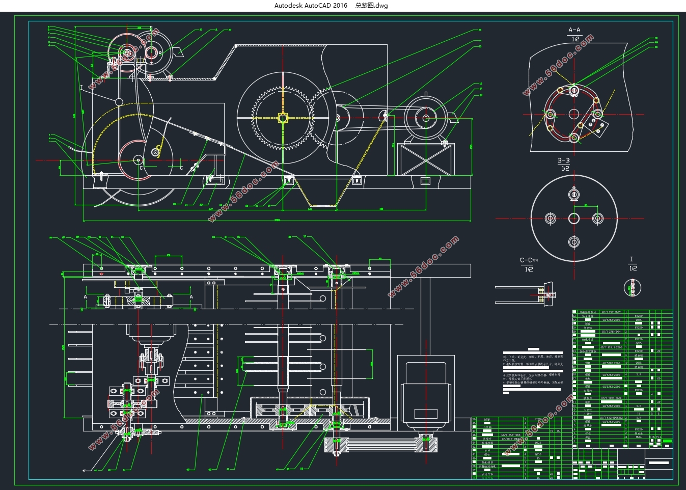
本机设计由拖拉机牵引前行,动力由电机输出,,实现对秸秆的收集粉碎掩埋作业。首先电机通过一对齿轮减速驱动链轮,链轮带动捡拾器滚筒旋转,由于主轴固定在滚盘上,主轴带动滚盘上四个弹齿轴做圆周运动,弹齿轴在滚盘内可自由转动,弹齿轴端连接一连杆,连杆一段在D型滚倒内转动,连杆在转过一定角度时弹齿杆也转过一定角度,故可以完成放齿、捡拾、升运、输送工作。
粉碎机由3kw电机驱动,由4根普通V带传动动力,再由一对齿轮同时带动两刀轴进行粉碎,物料落入料斗,料斗正下方下装有开沟器,底下土层顺铲尖铲壁到达上方,粉碎的秸秆正好进入锄铲式开沟器内部并达到土壤深处。
目录
摘要 I
ABSTRACT II
第一章 原始参数、技术参数及工艺路线 1
1.1 原始数据及技术参数 1
1.1.1本课题设计参数 1
1.1.2 技术参数 1
1.2工艺路线 1
第二章 弹齿捡拾器设计计算 3
2.1捡拾器结构尺寸设计 3
2.2弹齿设计 3
2.3电机选择 4
2.4传动装置的设计 4
2.4.1传动比的分配 5
2.4.2动力传动系统的运动及参数计算 5
2.4.3链传动设计计算 5
2.4.4齿轮传动设计计算 7
2.4.5轴的设计计算 8
2.5轨道的设计 11
第三章 输送装置设计 13
3.1导料板设计 13
3.2拨杆设计 13
第四章 粉碎装置设计计算 14
4.1粉碎机的选择 14
4.2锯片基本参数设计 14
4.3电机选择 14
4.4传动装置的设计 15
4.4.1传动比的分配 15
4.4.2传动装置的运动、动力参数计算 15
4.4.3带传动设计计算 16
4.4.4齿轮传动设计计算 17
4.4.5方轴的设计计算 19
第五章 落料及深埋装置设计计算 21
5.1料斗设计 21
5.2开沟器设计 21
第六章 机架设计结算 23
6.1机架设计 23
第七章 设备经济性分析 24
7.1设备生产制造成本分析 24
7.1.1材料成本 24
7.1.2辅材成本 24
7.1.3人工成本 24
7.1.4标准件成本 24
7.2设备使用成本分析 25
7.2.1耗能成本 25
7.2.2零件磨损更换 25
7.2.3操作成本 25
7.3综合成本分析 25
结束语 27
参考文献 28
致谢 29
|
