数控滚齿机主轴箱设计(含CAD零件图装配图)
来源:56doc.com 资料编号:5D27175 资料等级:★★★★★ %E8%B5%84%E6%96%99%E7%BC%96%E5%8F%B7%EF%BC%9A5D27175
资料以网页介绍的为准,下载后不会有水印.资料仅供学习参考之用. 密 保 惠 帮助
资料介绍
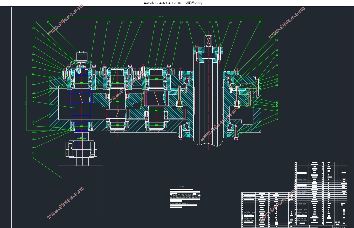
数控滚齿机主轴箱设计(含CAD零件图装配图)(任务书,开题报告,论文说明书10000字,CAD图5张)
摘要
主轴箱是机床的主要部件,是用于布置机床工作主轴及其传动零件和相应的附加机构的。主轴箱采用多级齿轮减速。箱内各个位置上的传动齿轮和传动轴把运动传到主轴上,使主轴获得规定的转速和方向。主轴箱传动系统的设计,以及主轴箱各部件的加工工艺直接影响机床的性能。
主轴箱为数控机床的主要传动系统,它包括电动机、传动系统和主轴部件。它与普通车床的主轴箱比较,相对来说比较简单,只有二级或三级齿轮变速系统。它主要是用以扩大电动机无级调速的范围,以满足一定恒功率、和转速的问题。
本课题主要研究的内容是,在确定加工工件的模数和直径后,计算出最大滚削力,然后选择电机,分配传动比,设计和校核各轴和零件,最后完成滚齿机主轴箱的设计。
关键字:数控车床 主轴箱 传动 齿轮
Design of CNC hobbing machine headstock
Abstract
Headstock are the main components of the machine, which is used to lay out the work spindle and transmission parts and corresponding additional institutions. Headstock adopts multilevel reduction gear. Each position inside the drive gear and drive shaft of the movement transmitted to the spindle, the spindle to obtain the specified speed and direction. Headstock drive system design and the various components of the headstock process directly affect the machine's performance.
CNC machine tool spindle box as the main drive system, which includes the motor, transmission and spindle assembly. And ordinary lathe headstock comparison is relatively simple, only two or three gear shifting system. It is mainly used to expand the range of variable speed motor to meet certain constant power, and speed issues.
The main subject of the content, in determining the modulus and workpiece diameter, calculate the maximum hobbling force, and then select the motor, transmission ratio distribution, design and check the shaft and parts to finalize the design of the headstock gear hobbling .
Keywords: CNC lathe;headstock;transmission;gear
原始设计参数
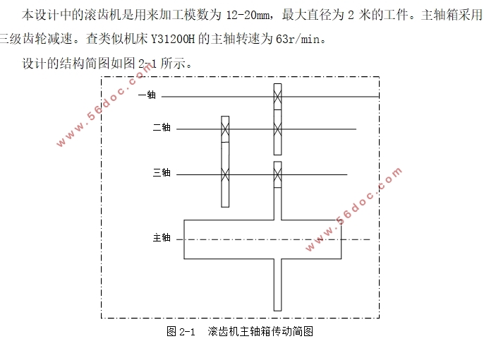
本设计中的滚齿机是用来加工模数为12-20mm,最大直径为2米的工件。主轴箱采用三级齿轮减速。查类似机床Y31200H的主轴转速为63r/min。


目 录
摘要 I
Abstract II
第一章 绪论 1
1.1 数控滚齿机发展历史 1
1.2 数控滚齿机主轴箱设计概述 2
1.3 数控滚齿机主轴箱设计的发展趋势 3
1.4 本章小结 3
第二章 总体方案设计 4
2.1 原始设计参数 4
2.2 最大滚削力的计算 4
2.3 电机的选型各级传动比的分配 5
2.3.1 电机选型 5
2.3.2 计算总传动比及分配各级传动比 6
2.4 本章小结 7
第三章 主轴箱主要零件的设计和校核 8
3.1 各轴上齿轮设计和校核 8
3.1.1 Ⅰ轴上的齿轮 8
3.1.2 Ⅱ轴上的齿轮 11
3.1.3 Ⅲ轴上的齿轮 14
3.2 各轴结构设计及轴上零件选型 16
3.2.1 Ⅰ轴的设计 17
3.2.2 Ⅱ轴的设计 18
3.2.3 Ⅲ轴的设计 20
3.3各轴强度的校核 22
3.3.1 Ⅰ轴的校核 22
3.3.2 Ⅱ轴的校核 25
3.3.3 Ⅲ轴的校核 28
3.4 轴承的寿命校核 31
3.5 本章小结 32
第四章 传动轴三轴的有限元分析 33
4.1有限元软件ABAQUS的简介 33
4.2三轴的有限元分析 34
4.3本章小结 39
总 结 40
附录 41
参考文献 46
|


