发动机连杆的锻模设计(含CAD图,SolidWorks冷锻件三维图)(任务书,开题报告,外文翻译,论文说明书13000字,CAD图5张,SolidWorks图1张)
摘要
本次毕业设计是完成发动机连杆的锻模设计。在设计之初先进行了资料的查阅,了解了目前主流的锻模模具的发展情况以及锻造工艺的优势,锻造在机器制造业中有着不可替代的作用,锻件的生产效率是相当高的,一个国家的锻造水平,反映了这个国家的机器制造业的水平,而且锻件的综合性能高,有着节约原材料和机械加工工时等优势。接着完成了对工件的分析,设计了几种工艺方法,并最终选定了使用拔长、开式滚挤、预锻、终锻工艺。设计中分析了各步的锻造工艺,根据实际工件的尺寸,计算机械加工余量、锻模件的公差、模锻斜度、圆角半径、锻锤吨位、毛边槽尺寸等。接着又进行了预锻和终锻模膛的设计。从而选定压力机,并且进一步得出了整体尺寸。最后绘制了预断(热锻件图)、终锻(冷锻件图)、连杆锤锻模图、切边模图模具装配图及零件图。
关键词:锤锻模;预锻;终锻
Abstrack
The graduation project is designed to complete the forging die of engine connecting rod. In the beginning of the design was first information access, understand the advantages of the current mainstream die mold developments and forging process, forging an irreplaceable role in the machine manufacturing industry, forging production efficiency is very high, a forging national level, it reflects the level of the country's machine building industry, and high overall performance forgings, with conservation of raw materials and machining work and other advantages. Then completed the work of analysis, design process for several, and finally selected the use of stretching, squeezing open roll, pre-forging, the final forging process. Design analysis of each step of the forging process, according to the size of the actual workpiece machining allowance calculation, die parts are within tolerance, forging slope, radius, hammer tonnage flash gutter size and so on. Then he conducted a final pre-forging and die boring design. Thus selected presses, and further obtain the overall size. Finally plotted prejudge (hot forging drawing), the final forging (cold forging drawing), connecting rod forging die diagram, trimming die view of the mold assembly drawings and parts of components.
Key Words:Hammer forging die; blocker; final forging
零件图分析
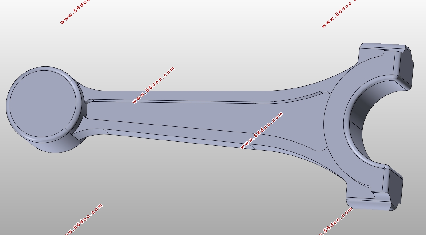
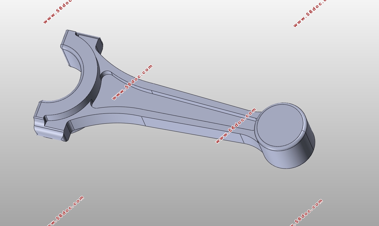
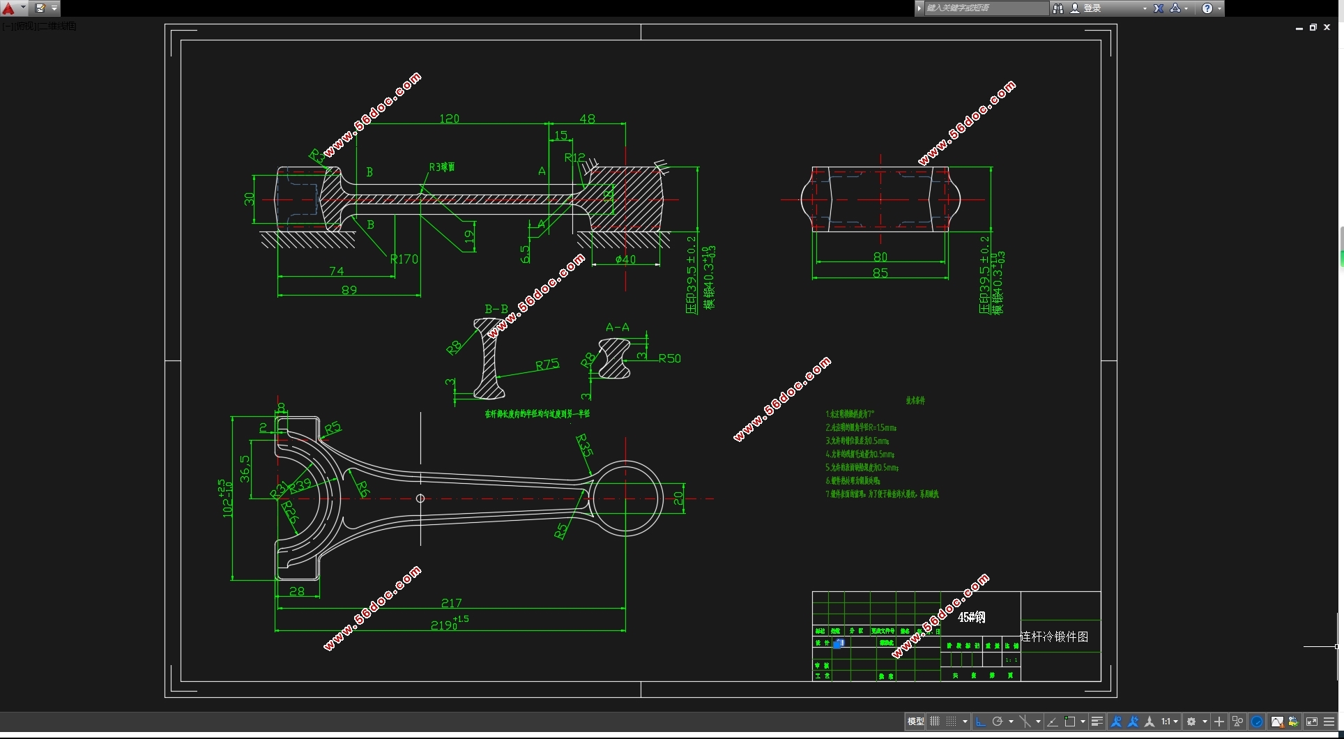
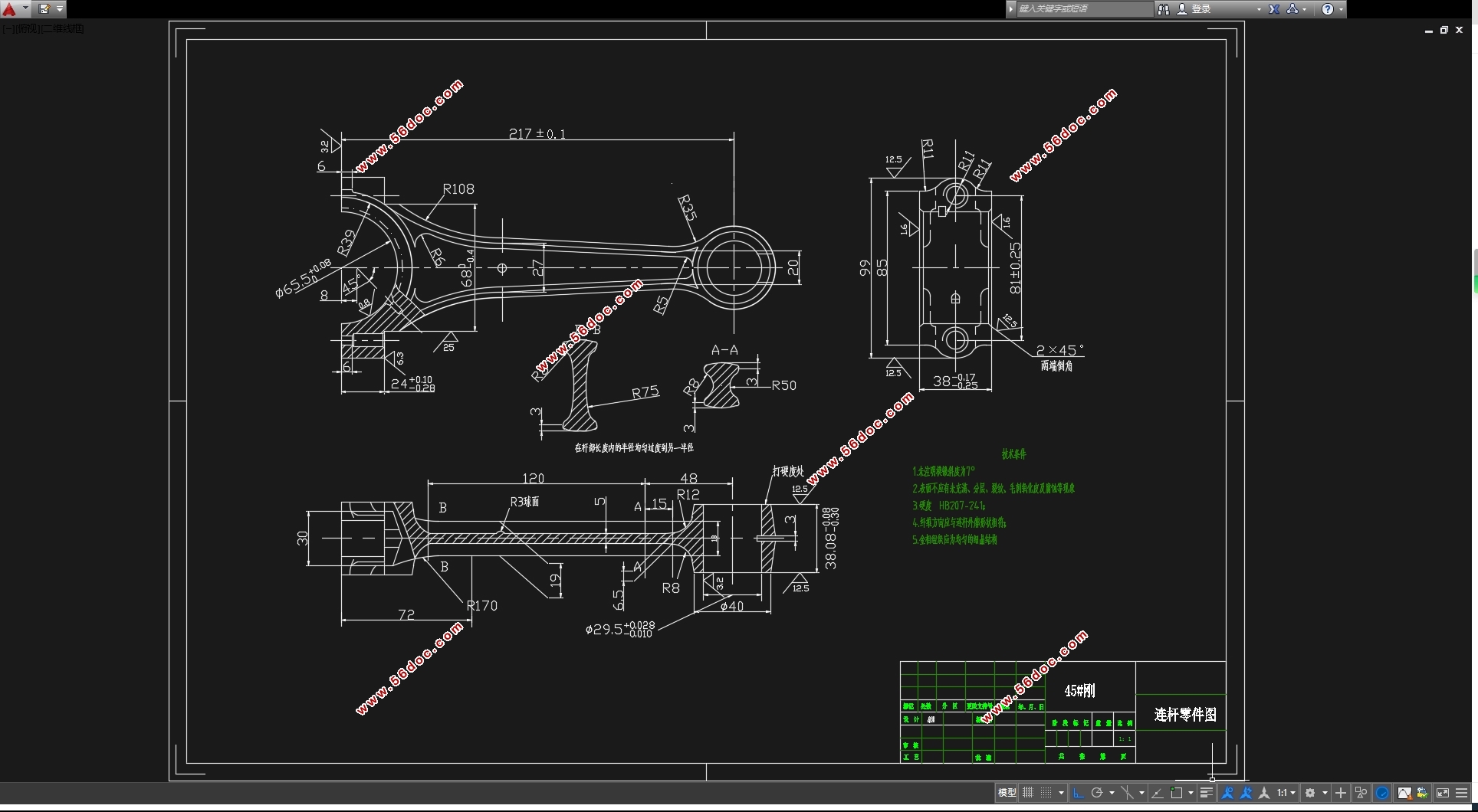
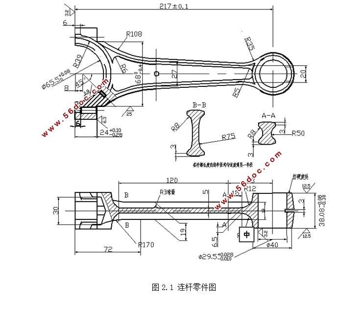
连杆在高速工作时,工作条件比较繁重,除和曲轴拐颈相连的半圆叉形部分以及通过与活塞相连接的小头部分需机械加工外,其他工字形截面和杆部部分不处理。零件图如图2.1所示。
技术要求:
①模锻斜度7°;
②表面不应该有未充满、分层、裂纹、毛刺、氧化皮及腐蚀现象;
③硬度:HB207-241;
④纤维方向应与连杆外轮廓形状相符;零件材料:45#;零件名称:连杆;
目录
第1章绪论 1
1.1模具和模具工业 1
1.2我国模具现状和发展前景 2
1.3锻造加工的优势 2
第2章连杆零件的分析 3
2.1连杆功能和结构特点 3
2.2零件图分析 3
第3章锤上模锻 5
3.1锤上模锻特点 5
3.2锤上模锻方式 5
3.3锤上锻模的工艺路线 6
第4章连杆的锻模设计 7
4.1锻件图的设计 7
4.1.1分模面位置的确定 7
4.1.2模锻件公差和余量 7
4.1.3模锻斜度 10
4.1.4圆角半径 11
4.1.5冲孔连皮 11
4.1.6锻件图的技术条件 11
4.2绘制锻件图 12
4.2.1锻件的主要参数 14
4.2.2确定锤锻吨位 15
4.2.3确定毛边槽形式和尺寸 16
4.3确定终锻模镗 17
4.4确定预锻模镗 18
4.5绘制计算毛坯图 18
4.6制坯工步选择 19
4.7确定坯料尺寸 19
4.8制坯工步模膛设计 22
4.8.1拔长模膛设计 22
4.8.2滚挤模膛设计 24
4.8.3模膛的布排 25
4.8.4错移力的平衡与锁扣的设计 26
4.8.5钳口设计 26
4.8.6模具强度设计 28
4.8.7燕尾与键槽尺寸 29
4.8.8连杆模锻工艺流程 29
4.9连杆切边模设计 32
第5章结论 36
参考文献 37
致谢 39
|
