新型液压泥炮装置设计(含CAD图)(任务书,开题报告,外文翻译,论文说明书10000字,CAD图3张)
摘 要
21世纪以来,在国家大力地推动下,我国各行业飞速发展,钢铁生产工业也实现全面的持续高速发展。同时,钢铁产能过剩的问题也逐渐突显出来。一直以来,随着生产发展飞速发展,我国钢铁炼钢工业不断地在进行技术改造,基本实现了炼钢工艺流程的可持续、绿色、紧密以及生产设备的高效率、巨型化以及自动化。
而液压泥炮作为高炉炼铁生产中不能缺少的重要冶炼装置,更是钢铁行业中非常重要的一种装置。
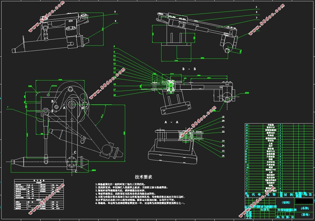
本文根据我国钢铁生产技术要求,在给定部分技术性能参数的基础上,设计了泥炮总体结构和关键组成部分。在此基础上,根据各部分组成,绘制了泥炮总装二维图,并着重表达了控制连杆部件的装配关系,及部分零件的零件图。
本文的特色:用四连杆机构控制打泥机构运动,增强回转运动平稳和准确性。
关键词:炼钢;液压;泥炮;连杆;回转机构
Abstract
Since the 21st century, under the impetus of national macro-control policies and measures, China's economy has developed at a high speed, and the steel-making industry has also achieved sustained and rapid development. At the same time, the problem of overcapacity in steel has gradually emerged. All along, with the rapid development of production, China's steelmaking industry is constantly undergoing technological transformation, which basically realizes the sustainable, green and compact steelmaking process and the high efficiency, large-scale and automation of production equipment.
The mud gun is an indispensable important metallurgical equipment in the blast furnace iron making process, and it is also a very important equipment in the steel industry.
According to the technical requirements of China's steel production, based on the given technical performance parameters, the overall structure and key components of the mud gun are designed. On this basis, according to the composition of each part, a two-dimensional map of the general assembly of the mud cannon is drawn, and the assembly relationship of the control link components and the parts drawing of some parts are emphasized.
The characteristics of this paper: the four-bar linkage mechanism is used to control the movement of the mud-soiling mechanism to enhance the smoothness and accuracy of the rotary motion.
Key Words:Hydraulic;Mud gun;connecting rod;slewing mechanism


目录
第1章 绪论 5
1.1 研究目的及意义 5
1.2 国内外研究现状 5
1.3 液压泥炮的组成 6
1.3.1机械部分 6
1.3.2液压部分 7
1.4 研究内容 7
第2章总体结构设计 8
2.1连杆机构 8
2.2回转机构 9
2.3打泥机构 9
图2.1 打泥机构 9
2.4液压系统 9
第3章 机构设计计算 10
3.1打泥机构的计算 10
2.1.1泥缸直径和打泥油缸直径确定 10
2.1.2泥缸壁厚和外径确定 11
3.2斜底座的设计 12
3.3回转机构的设计计算 13
1.炮身 2.转臂 3.拉杆 4.V型杆 5.油缸活塞杆 6.辅助连杆 14
图 回转机构简图 14
3.3.1 连杆受力分析 14
3.3.2 转炮油缸活塞杆受力分析 15
第4章 部分零部件校核 19
4.1 泥缸筒强度校核 19
D -缸筒内径,m; 19
4.2 打泥机构活塞杆的校核 20
D ——缸筒直径,m 20
第5章 液压系统设计 21
5.1 液压系统原理 21
5.2 液压泵的选取 21
4.2电机的选取 22
P1、p2——一次循环运动中两个阶段分别所需的功率; 22
t1、t2——一次循环运动中两个阶段分别所需的时间; 22
Q1、Q2——两个油缸的零流量; 22
第5章 总结与展望 23
参考文献(黑体小二号) 25
致 谢 27
|


