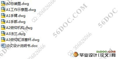
曲轴搬运机械手的设计(液压)(设计说明书20000字,cad图纸7张)
摘 要:本课题设计的曲轴搬运机械手采用关节型坐标系、全液压驱动,具有手臂伸缩、俯仰、回转和手腕回转四个自由度,以及手指的抓取动作。执行机构相应由手部抓取机构、手腕回转机构、手臂伸缩机构、手臂俯仰机构、手臂回转机构和各定位装置等组成,每一部分均由液压缸驱动与控制。本课题归纳了工业机械手和曲轴搬运机械手研究中的关键问题,分析了工业机械手的研究现状和发展趋势,讨论了设计工业机械手及曲轴搬运机械手的方案。在此基础上,对工业机械手及曲轴搬运机械手的进一步研究进行了展望。
关键字:机械手;手臂伸缩结构;机身摆动结构;液压泵;液压缸;
Design of the Crankshaft Handling Robot
Abstract:The design of the crankshaft at this topic uses articulated robotic coordinate system, hydraulic drive, with four free degrees of arms stretching, pitch, rotation and wrist rotation, and the fingers crawl action. The corresponding actuator body makes up by the hand grab, wrist rotation body, arms stretching institutions, agencies pitching arm, the arm rotating mechanism and the positioning device and other components., each part of the drive and control by the hydraulic cylinder. This paper presents the development of a low cost experimental telerobotic system built up with local means in an emerging country . From a remote site, a webcam sends images of a robot manipulator through Internet to the control site where a human operator remotely monitors this robot in order to achieve pick-and-place tasks. Some control modes have been implemented and tested such as mouse-click, image-based and gesture-based modes.
Key words: Manipulator; arm telescopic structure; body swing structure; hydraulic pump; hydraulic cylinder
设计要求
某生产线上搬运工件原由人工完成, 劳动强度大、生产效率低。为了提高生产线的工作效率, 降低成本, 使生产线发展成为柔性制造系统, 适应现代自动化大生产, 针对具体生产工艺, 利用机器人技术, 设计用一台搬运机械手代替人工工作。
该机械手能完成如下的动作循环:手臂前伸→手指夹紧抓料→手臂上升→手臂缩回→机身回转180度→手腕回转90度→手臂下降→手臂前伸→手指松开→手臂缩回→机身回转复位→手腕回转复位→待料。
目 录
摘 要 1
关键字 1
1 前言 2
1.1 工业机器人(机械手)的概述 2
1.1.1 工业机器人的发展 2
1.1.2 工业机器人的分类 2
1.1.3 工业机械手的应用 3
1.2 设计问题的提出 4
2 机械手的总体设计 4
2.1 机械手的组成及各部分关系概述 4
2.2 机械手的设计分析 4
2.2.1 设计要求 4
2.2.2 总体设计任务分析 5
2.2.3 总体方案拟定 7
3 机械手结构的设计分析 7
3.1 末端操作器的设计分析 7
3.1.1 末端操作器的概述 7
3.1.2 末端操作器结构的设计分析 8
3.2 手腕的设计分析 8
3.3 手臂的设计分析 8
3.4 机身和机座的设计分析 9
4 机械手各部件的载荷计算 10
4.1 设计要求分析 10
4.2 手指夹紧机构的设计 10
4.2.1 手指夹紧机构载荷的计算 10
4.3 手臂伸缩机构载荷的计算 11
4.4 手臂俯仰机构载荷的计算 12
4.5 手腕摆动机构载荷力矩的计算 13
4.6 机身摆动机构载荷力矩的计算 14
4.7 初选系统工作压力 14
5 机械手各部件结构尺寸计算及校核 15
5.1 手指夹紧机构结构尺寸的确定 15
5.4 手腕摆动机构的确定 18
5.5 机身摆动机构的确定 19
5.5.1强度校核 19
5.6 弯曲稳定性校核 20
6 液压系统的设计 21
6.1 液压缸或液压马达所需流量的确定 21
6.3 液压缸或液压马达主要零件的结构材料及技术要求 22
6.3.1 缸体 22
6.3.2 缸盖 23
6.3.3 活塞 23
6.3.4 活塞杆 23
6.3.5 液压缸的缓冲装置 23
6.3.6 液压缸的排气装置 24
6.4 制定基本方案 24
6.4.1 基本回路的选择 24
6.5 液压元件的选择 25
6.5.1 液压泵的选择 25
6.5.2 液压泵所需电机功率的确定 26
6.5.3 液压阀的选择 27
6.5.4 液压辅助元件的选择原则 27
6.5.5 油箱容量的确定 29
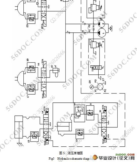
6.5.6 液压原理图 29
7 结论 32
参考文献 32
致 谢 33
附录 35
附录1 图纸列表 35
附录
附录1 图纸列表
序号 名称 图号 大小 张数
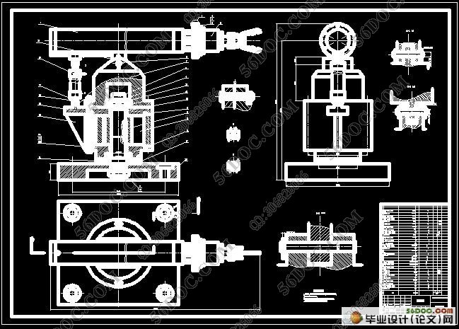
1 机械手 J-00 A0 1
2 手臂 J-00-01 A1 1
3 手部 J-00-02 A1 1
4 俯仰机构 J-00-08 A2 1
5 俯仰缸活塞杆 J-00-08-02 A3 1
6 法兰 J-00-02-01 A3 1
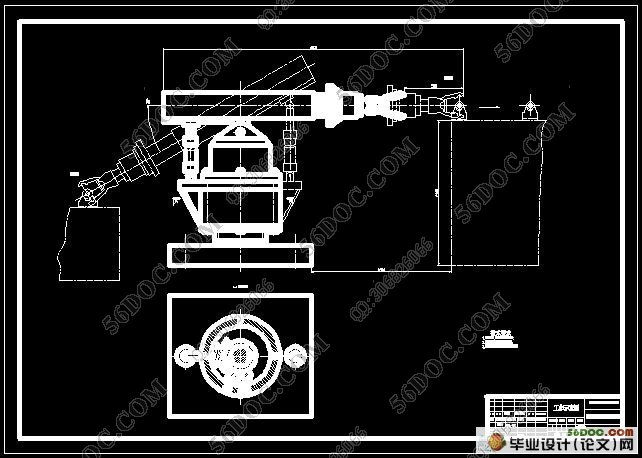
7 工作示意图 A1 1
|
