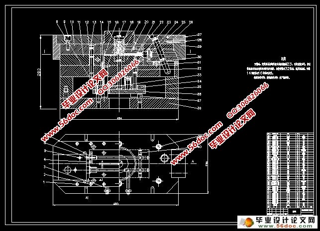
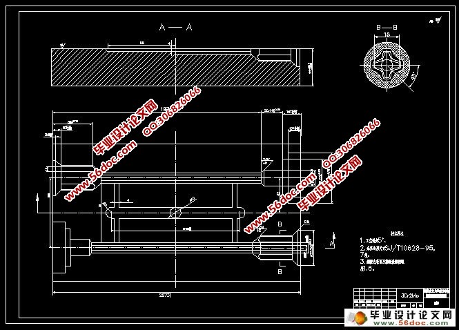
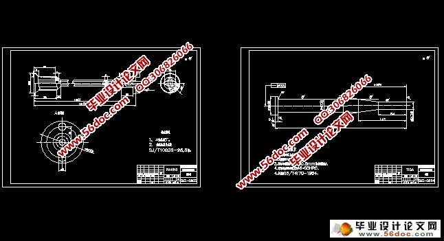
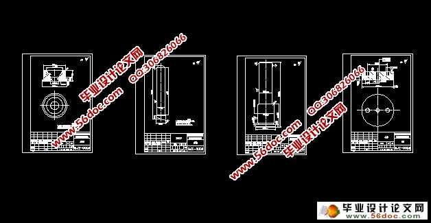
塑件注射工艺分析及模具设计(含CAD零件图和装配图)(选题审批表,任务书,开题报告,中期检查表,论文说明书15200字,CAD图8张)
摘 要:根据给定塑件轴的尺寸和结构要求,对塑件进行工艺的分析和比较,最终设计出一幅一模两腔的注塑模具。改设计从产品结构工艺性,具体模具结构出发,对模具结构出发,对模具的浇注系统、模具成型部分的结构、顶出系统、冷却系统、注塑机的选择及有关的校核、都有详细的设计,同时简单的编制了模具的加工工艺。整个设计过程表明该模具能够达到此塑件所要求的加工工艺。设计出来的模具以满足工业生产需求,实现塑件轴的高效、自动化生产。
关键词:塑件轴;注射模具;加工工艺;零件图
Analysis of the Injection Process and Design of the Mold Plastics Shaft
Abstract:According to the given plastic shaft size and structural requirements,the technology of plastic parts for analysis and comparison,the final design of an injection mold of a mold with two cavity.The design process from the product structure,the concrete structure of the mold,the mold casting system,mold forming part of the structure ,the roof system,cooling system,the choice of injection molding machine and related parameters of the check,have the detailed design,at the same time,simple preparation of the mold process .The whole design process that the mold can achieve the required pieces of plastic,processing technology.The design of the mold can meet the industrial production requirements, realize the plastic shaft efficient and automated production.
Key Words: Plastic axis; Injection mold; Processing technology; Parts drawing
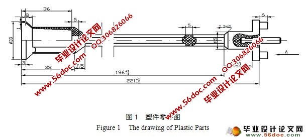
该零件是一个较长的轴类塑件,左侧是一个凹槽,用到侧抽芯机构;中间部分截面是一个十字轴;右侧安放嵌件。由于塑件较长,总体结构较复杂,需要用到的型芯、型腔加工难度比较大,而且各部分壁厚不是很均匀,很容易产生填充不足的缺陷,为此需要适当提高注射压力和注射速度,合理设定注射行程,进行成型工艺分析。
目 录
摘要…………………………………………………………………………………………1
关键词………………………………………………………………………………………1
1 前言………………………………………………………………………………………2
1.1 研究意义…………………………………………………………………………2
1.2 国内外研究现状…………………………………………………………………4
1.3 发展方向…………………………………………………………………………5
2 塑件的工艺分析…………………………………………………………………………5
2.1 塑件的组成工艺分析……………………………………………………………5
2.2 塑件成型工艺性分析……………………………………………………………6
2.2.1 塑件尺寸结构分析………………………………………………………6
2.2.2 塑件尺寸精度分析………………………………………………………6
2.2.3 表面质量析………………………………………………………………7
2.2.4 脱模斜度…………………………………………………………………7
2.3 塑件的体积重量…………………………………………………………………7
2.4 浇注系统的设计…………………………………………………………………8
3 型腔数的确定及浇注系统的设计………………………………………………………8
3.1 分型面的分析……………………………………………………………………8
3.2 型腔数的确定…………………………………………………………………10
3.3 确定型腔的排列方式…………………………………………………………10
3.4 浇注系统的设计………………………………………………………………10
3.4.1 主流道的设计…………………………………………………………10
3.4.2 分流道的设计…………………………………………………………10
3.4.3 浇口的设计…………………………………………………………11
4 侧向分型与抽芯机构的设计……………………………………………………12
4.1 斜导柱的设计………………………………………………………………12
4.1.1 斜导柱的基本形式……………………………………………………12
4.1.2 斜导柱倾斜角的选择…………………………………………………13
4.1.3 斜导柱长度的计算……………………………………………………14
4.1.4 斜导柱直径的计算……………………………………………………15
4.2 侧滑块的设计…………………………………………………………………15
4.3 导滑槽的设计…………………………………………………………………15
4.4 锲紧块的设计…………………………………………………………………16
5 模具成型零件的设计………………………………………………………………16
5.1 凹模结构形式的选择…………………………………………………………16
5.2 凹模及型芯工作尺寸的计算…………………………………………………16
5.2.1 型腔和型芯尺寸计算…………………………………………………16
6 推出机构的设计与计算……………………………………………………………17
6.1 推出机构设计的原理…………………………………………………………17
6.2 脱模力的计算…………………………………………………………………18
6.3 推杆直径的计算………………………………………………………………18
7 温度调节系统…………………………………………………………………………18
8 注射机与模具各参数的校核…………………………………………………………19
8.1 注射量的校核…………………………………………………………………19
8.2 锁模力的校核…………………………………………………………………19
8.3 安装参数的校核………………………………………………………………19
9 成型零件加工工艺……………………………………………………………………20
10 结论 …………………………………………………………………………………21
参考文献……………………………………………………………………………………21
致谢…………………………………………………………………………………………22
附录…………………………………………………………………………………………23
|
