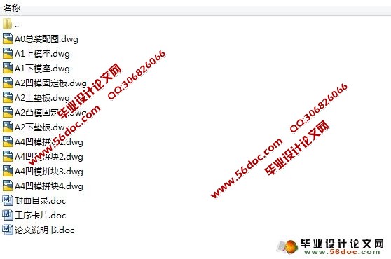
导电接片模具设计(选题审批表,任务书,开题报告,中期检查表,论文说明书12100字,CAD图11张)
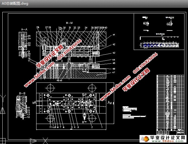
摘 要:本次冲压模具设计过程中结合生产实际,运用冲压成形的基本理论对该制件的基本工序的特点、性质、规律进行了分析、研究和探讨,模具选用确定为多工位级进模。分析零件的冲压工艺性,并根据制件结构特点合理安排工序顺序。以落料、拉深、折弯、压扁工序为重点确定冲压工艺方案,计算了毛坯排样、冲压力、刃口尺寸等,详细介绍了模具结构设计及常见问题处理方法。
关键词:导电片;多工位级进模;工艺分析
Mold Design of Conductive Meet Piece
Abstract:This mold design process combined with the actual production, use stamping forming of the basic theory to analysis, research and investigate the parts of the basic process characteristics, nature and law, die select as multi-position progressive die. Analysis of parts of the stamping process, and according to the product structure characteristic of reasonable arrangement procedure. The blanking, drawing, bending, flattening process is focused on determining the stamping process program, a rough calculation of the layout, punching pressure, cutting edge dimensions etc., introduced the die structure design and treatment of common problems in detail.
Key words:conductive film; the multi-position progressive die mold; process analysis
零件的工艺分析
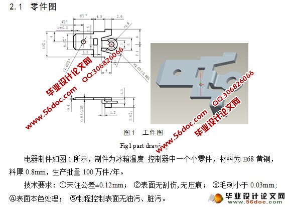
该零件材料为H68黄铜,抗剪强度τ=240MPa,抗拉强度 =300MPa,伸长率δ=40%,屈服点 =100MPa。尺寸公差、精度要求较高,形状小而复杂, 产量大是该零件特点,它给模具结构设计与冲压生产提出了特殊的要求。从结构分析, 零件成形主要有冲裁、L 型弯曲、Z 型弯曲、压扁、切断等多道工序, 而且头部的Z 型弯曲上有小孔, 若采用单工序多副模生产比较麻烦,质量难以保证,很不经济和, 因此采用多工位级进模, 可以利用载体在各工位之间输送工件, 自动实现定位, 自动脱模, 很少受到人为因素干扰, 工件的精度高, 质量可靠。因此综合考虑采用多工位级进模在高速压力机生产比较合理。 在满足生产的前提下, 尽可能地简化模具结构, 降低加工难度及成本。凹模最小宽度B=1≥1.2t(t为材料厚度,其中t=0.8mm) ,冲孔时有最小尺寸为φ1.65 ,冲孔时因受凸模强度的限制,孔的尺寸不应太小。冲孔的最小尺寸取决于材料性能,凸模的强度和模具结构等.查得圆形孔最小值得 d=0.9t=0.9×0.8=0.72mm<φ1.65 所以满足工艺性要求。
冲裁件孔与孔之间:孔与边缘之间的距离受模具的强度和冲裁件质量的制约,其值不应过小,一般要求C≥(1~1.5)t,C′>(1.5~2)t所以由冲件图可知
C =15.6-8-2.03/2-1.65/2=5.76>1×0.8=0.8
C′=(4.6-2.03)/2=1.285>1X0.8=0.8
由以上可知孔与孔之间距离C 满足工艺性要求, 最小孔与边缘之间的距离 C′同样满足工艺性要求。
目 录
摘要…………………………………………………………………………………………1
关键词………………………………………………………………………………………1
1 前言………………………………………………………………………………………1
2 工件的冲压工艺分析……………………………………………………………………3
2.1 零件图……………………………………………………………………………3
2.2 零件的工艺分析…………………………………………………………………4
3 零件冲压工艺方案的确定………………………………………………………………4
3.1 排样方案设计……………………………………………………………………4
3.1.1 零件展开…………………………………………………………………4
3.1.2 排样设计…………………………………………………………………5
4 工艺计算…………………………………………………………………………………7
4.1 工艺与设计计算…………………………………………………………………7
4.1.1 冲裁力计算………………………………………………………………7
4.1.2 弯曲模弯曲力计算………………………………………………………8
4.1.3 卸料力……………………………………………………………………9
4.1.4 推件力……………………………………………………………………9
4.1.5 压力机的确定……………………………………………………………9
4.2 压力中心的计算…………………………………………………………………9
4.3 计算模具刃口尺寸……………………………………………………………10
4.3.1 凸、凹模分开加工时,其尺寸公差的确定……………………………10
4.3.2 凸、凹模配合加工时,其尺寸公差的确定……………………………11
4.3.3 凸、凹模刃口尺寸计算…………………………………………………11
4.3.4 弯曲刃口尺寸计算……………………………………………………15
5.模具的结构设计…………………………………………………………………………16
5.1 微调结构………………………………………………………………………16
5.2 快换安装固定结构……………………………………………………………16
5.3 导正销的特殊结构……………………………………………………………17
5.4 安全装置………………………………………………………………………18
5.5 定位销与小导柱的设计………………………………………………………18
5.6 强力弹簧压料机构……………………………………………………………19
5.7 凹模和卸料板的特殊结构……………………………………………………19
5.8 凹模刃口设计…………………………………………………………………19
6 零件的设计与选用……………………………………………………………………19
6.1 确定主要的零件材料及尺寸…………………………………………………19
6.1.1 凹模……………………………………………………………………19
6.1.2 凸模……………………………………………………………………19
6.1.3 上、下垫板……………………………………………………………19
6.1.4 模座……………………………………………………………………19
6.1.5 凸模固定板……………………………………………………………20
6.2 模柄的设计与选用……………………………………………………………20
6.3 螺钉规格的选用………………………………………………………………20
7 压力机的确定…………………………………………………………………………21
参考文献 …………………………………………………………………………………21
致谢……………………………………………………………………………………… 22
|
