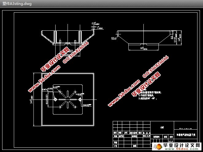
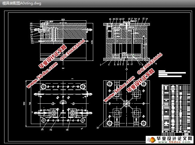
车载空气净化器下壳塑料模具设计(选题审批表,任务书,开题报告,中期检查表,论文设计说明书15000字,CAD图纸18张)
摘 要:随着生活水平的提高,汽车早已成为我们家居、旅行中不可或缺的交通工具。然而我们在享受着汽车所带来的方便的同时,却也遭受到了汽车室内空气污染为我们的健康造成的危害。故本次基于此现象,选择了车载空气净化器下壳模具的设计。
随着中国塑料工业的发展,近几年来中国塑料机械工业的年增长率都在30%左右,利润率增长也远高于工业总产值的增长,是中国机械行业中增长最快的产业之一。目前中国生产的塑料加工机械已可以满足国内的基本需要而塑料模具是其中发展较快的种类,因此,研究注塑模具对了解塑料产品的生产过程和提高产品质量有很大意义。近十年来,注射模CAD技术在不断进行理论和实验研究的同时,十分注意向实用化阶段发展,一些高水平的商品软件逐步推出,并在推广和实际使用中不断改进、提高和完善[5]。
本设计介绍了注射成型的基本原理,特别是单分型面注射模具的结构与工作原理,对注塑产品提出了基本的设计原则;详细介绍了冷流道注射模具浇注系统、温度调节系统和顶出系统的设计过程,并对模具强度要求做了说明;同时,在模具设计中,为增加适当的难度,选择了有侧抽心机构的产品下改进行模具设计制造。并且采用了活动镶件进行脱螺纹。
通过本设计,可以对注塑模具有了更深入的认识,注意到设计中的某些细节问题,了解模具结构及工作原理。本次设计不仅巩固了我的专业知识,更锻炼了我分析问题、处理问题的能力,为我走向工作岗位奠定了良好的基础。
关键词:塑料模具;参数化;镶件;分型面
Design of Plastic Mold of Car Air Purifier Device Shell
Abstract:, Taking a trip early in the necessary pileup, the automobile has become our house to reside , along with life the exaltation of the level. However at the time of enjoying the convenient of automobile, we are also suffering with the air pollution of automobile as a result in healthily of endanger . according to this phenomenon , It’s time to choose the car to carry the design of the air cleaner and its outer shell molding tool .
Plastic industry grows to one of quickest industry classes in the world today, but casts the mold is developing quickly. therefore , the research of casting the mold to understand the plastic product the production process and improves the product quality takes a very big significance. Over the past decades, the promotion and the actual using are improved with the gradual introduction and improvement of a high level of commercial software,along with CAD technology of injection mold in the ongoing theoretical and experimental research. With great attention on the practical stage, This design introduced the injection taking the shape of basic principle. dividing from the profile to inject the mold, the structure and the principle of work , casting the product to propose the basic principle of design is especially single; Introduced in detail, the injection evil spirit mold of cold flow channel pours the system, the temperature which has given the explanation to request of the mold intensity controls the system and goes against the system of design process; Meanwhile, choosing to have the side to take out the heart organization and take off the product of the thread organization to achieve the design of molding tool manufacturing under the improvement are in the design of molding tool. Its appropriate difficulty of increment to take off the thread organization to adopt the wheel gear and take off the thread method to give the realization.
Through this design , casting the mold to have a preliminary understanding , noting in the certain detail question of design and understanding the mold structure and the principle of work are possible. This design not only reinforces my expertise ability and problem solving skills, but also laid a good foundation for me to go to work.
Key words:The plastic mold ; the parametrization ; inlays ; divides the profile
本次设计外壳塑件材料选用ABS,ABS是一种具有良好综合性能的工程塑料,它具有聚苯乙烯的良好塑性、聚丁二烯的韧度、聚苯烯腈的化学稳定性和表面硬度,其抗拉强度可达35~50MPa。ABS的耐候性是它的另一个优点,一般ABS塑件的使用温度范围为-40~100°C,这正是本塑件最适宜的使用温度范围。
ABS塑料具有一定的吸湿性(含水量为0.3%~0.8%),成型时会在制件上产生斑痕、云纹、银丝、气泡等缺陷,故在注射成型之前应进行干燥处理。ABS熔体中具有中等黏度特性,流动性好。设定料温在200~240°C之间,模温在60°C左右。
塑料密度 =1.02~1.16 g/cm ,弹性模量E=1.4 10 MPa,成型收缩率 =0.4%~0.7%,泊松比 =0.35[3]。
2.2 塑件的相关计算
塑件体积 = 45.2×4=180.8cm
塑件密度 = 1.05g/cm
塑件质量 = 189.84g
流到凝料质量= 0.2x189.84=37.968g
流到凝料体积= 0.2x180.8=36.16cm
浇筑系统所需的塑料质量=189.84+37.968=227.808g
浇筑系统所需的塑料体积=180.8+36.16=216.96cm
流到凝料质量可以按照塑件质量的0.2倍来估算[1]。
目 录
摘要 …………………………………………………………………………………1
关键词 ……………………………………………………………………………1
1 前言……………………………………………………………………………………2
2 塑件的基本数据……………………………………………………………3
2.1 塑件材料的选择………………………………………………………………3
2.2 塑件的相关计算……………………………………………………………… 3
3 注射机的选择及相关参数的校核……………………………………………………4
3.1 型腔数量的初步确定…………………………………………………………4
3.2 注射剂型号的确定……………………………………………………………4
3.3 型腔数目的校核……………………………………………………………5
3.3.1 由注射机额定锁模力校核型腔数量n………………………………5
3.3.2 由注射机的最大注射量校核型腔数量n……………………………5
3.4 型腔的排列方式………………………………………………………………5
3.5 注射机相关参数的校核………………………………………………………6
3.5.1 最大注射量的校核……………………………………………………6
3.5.2 锁模力的校核………………………………………………………7
3.5.3 注射压力的校核……………………………………………………7
3.5.4 开模行程………………………………………………………8
4 分型面的选择与浇注系统设计……………………………………………………8
4.1 分型面的选择…………………………………………………………………8
4.2 浇注系统的设计……………………………………………………………9
4.2.1 定位圈的尺寸设计……………………………………………………9
4.2.2 主流道部分的尺寸设计………………………………………………9
4.2.3 浇口的尺寸设计………………………………………………………10
4.2.4 分流道的尺寸设计……………………………………………………12
4.2.5 计算体积流率………………………………………………………12
4.2.6 流程比校核………………………………………………………13
4.2.7 注射时间…………………………………………………………13
4.2.8 校核剪切速率………………………………………………………13
4.2.9 浇注系统的平衡……………………………………………………13
4.2.10 冷料穴的设计………………………………………………………14
5 成型零部件的设计……………………………………………………………14
5.1 型芯、型腔的结构设计……………………………………………………14
5.2 影响工作尺寸的因素…………………………………………………………15
5.2.1 塑件的收缩率波动……………………………………………………15
5.2.2 塑件的公差…………………………………………………………15
5.2.3 模具制造误差…………………………………………………………15
5.2.4 模具的磨损量…………………………………………………………15
5.2.5 模具在分型面上的合模间隙…………………………………………15
5.3 成型零件工作尺寸的计算……………………………………………………15
5.3.1 型腔径向尺寸的计算…………………………………………………16
5.3.2 型腔深度的计算………………………………………………………16
5.4 成型零部件的强度与刚度计算………………………………………………17
5.4.1 成型零部件强度、刚度计算需考虑的问题…………………………17
5.4.2 型腔侧壁厚度的计算…………………………………………………17
5.4.3 型腔腔底厚度的计算…………………………………………………18
6 导向机构及排气系统设计……………………………………………………18
6.1 导向机构设计………………………………………………………………18
6.1.1 导柱……………………………………………………………………18
6.1.2 导套……………………………………………………………………19
6.2 排气系统……………………………………………………………………19
7 冷却系统的设计………………………………………………………………………20
8 侧向分型抽芯机构设计………………………………………………………………21
8.1 主要参数的确定………………………………………………………………22
8.1.1 抽芯距S ………………………………………………………………22
8.1.2 斜导柱的倾角α ……………………………………………………22
8.2 侧向抽芯机构的结构设计要点………………………………………………22
8.2.1 斜导柱 ………………………………………………………………22
8.2.2 滑块 …………………………………………………………………23
8.2.3 滑块与导滑槽 ………………………………………………………23
8.2.4 滑块定位装置 ………………………………………………………24
8.2.5 锁紧块 ………………………………………………………………24
9 结论……………………………………………………………………………24
参考文献 ……………………………………………………………………………26
致谢 ………………………………………………………………………………27
|


