塑料齿轮三维模具设计(含CAD零件图装配图,ProE三维图)
来源:56doc.com 资料编号:5D13601 资料等级:★★★★★ %E8%B5%84%E6%96%99%E7%BC%96%E5%8F%B7%EF%BC%9A5D13601
资料以网页介绍的为准,下载后不会有水印.资料仅供学习参考之用. 密 保 惠 帮助
资料介绍
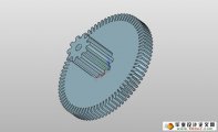
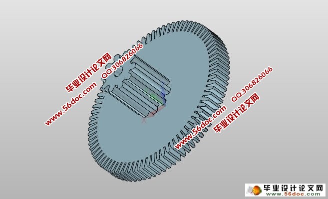
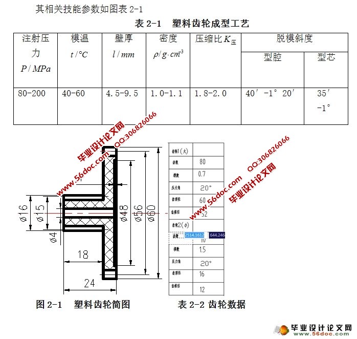
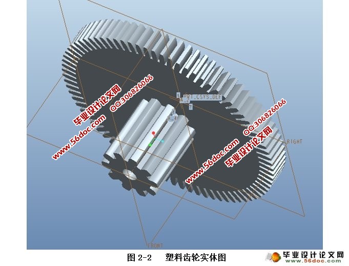
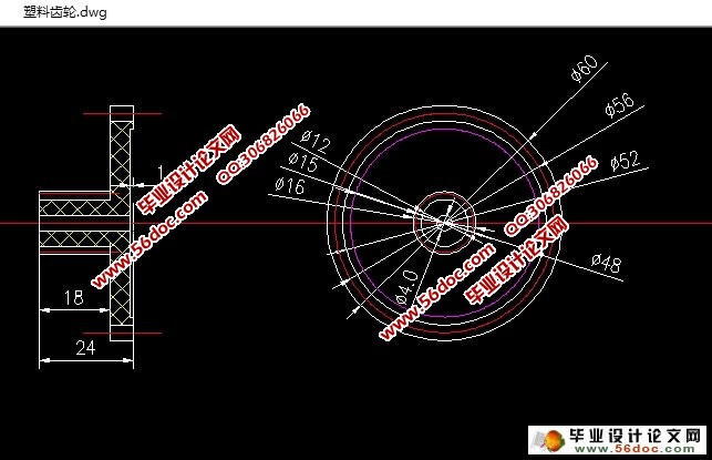
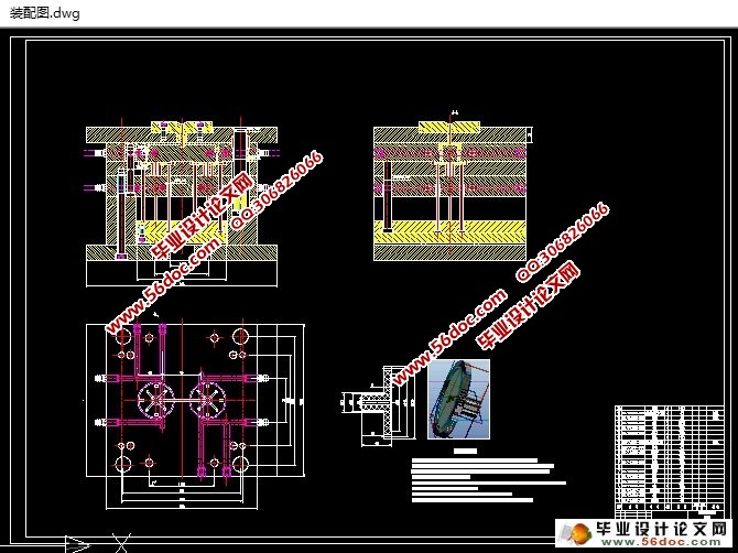
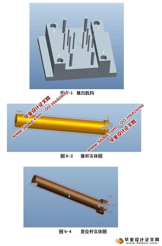
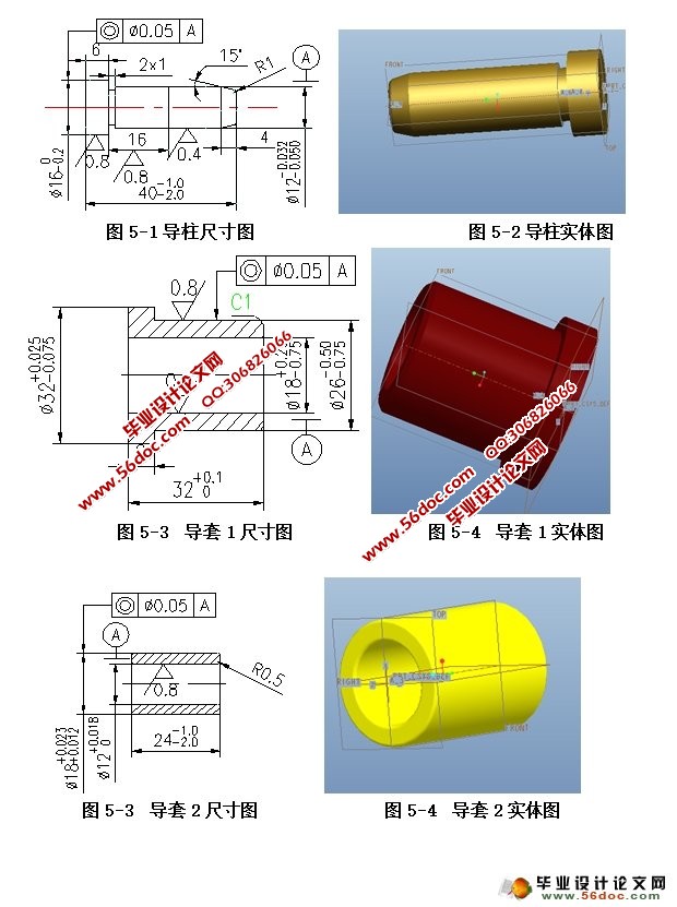
塑料齿轮三维模具设计(含CAD零件图装配图,ProE三维图)(文献综述,设计说明书15000字,CAD图6张,ProE三维图)
3 d mold design for plastic gears
摘 要
本课题是塑料齿轮三维模具设计,选用材料材料 ,通过注塑来使塑料齿轮成型。塑料齿轮是将双联齿轮作为设计模型,将注射模具的相关知识作为依据,阐述塑料注射模具的设计过程。
本设计对双联齿轮进行的注塑模设计,利用CAD软件对塑料齿轮尺寸形状大小进行设计,同时通过使用Pro/E软件对塑料齿轮进行高效而且清晰实体分析,同时通过要求与国家标准,制出一件符合要求的塑料齿轮塑件
进行了平面与实体设计,然后通过塑件结构进行了工艺分析,确定了注射成型工艺过程并对各个具体部分进行了详细的计算和校核。
关键词:塑料模具; 注射成型; 模具设计
ABSTRACT
This topic is the 3 d mold design for plastic gears, selects material, material through to make plastic gear injection molding. Plastic gear is to duplicate gear as a design model, the injection mold of the related knowledge as the basis, elaborated the design of plastic injection mould process.
This design of duplex gear injection mold design, plastic gear size shape size to make use of CAD software design, at the same time through the use of Pro/E software to efficient and clear plastic gears entity analysis, through requirements and national standards, at the same time make a conform to the requirements of the plastic gear plastic parts
Has carried on the plane and physical design, and then through the technology analysis, plastic parts structure determines the injection molding process and to each specific part carried on the detailed calculation and checking.
Keywords: plastic mold; Injection molding; Mold desig
目 录
摘 要 2
第一章 绪论 1
1.1 模具的地位与应用 1
1.2 我国的模具进程 1
1.3 选题依据及意义 2
第2章 塑料齿轮的工艺分析 4
2.1 塑料齿轮材料性能的分析 4
2.1.1 塑料齿轮成型特性 4
2.1.2 塑料齿轮成型工艺 4
2.2 塑料齿轮的结构工艺性 6
2.2.1 模具脱模斜度与表面粗糙度及塑料齿轮壁厚 6
2.2.2 塑料齿轮尺寸及公差 6
第三章 注射机的选择 7
3.1 型腔数的确定 7
3.2 注射量的校核 8
3.3 锁模力校核 8
3.4 注射压力的校核 8
3.5 开模行程的校核 9
第4章 注射模的结构设计 10
4.1 型腔的布局 10
4.2 分型面的确定 10
4.3 浇注系统设计 11
4.3.1 主流道及浇口套的设计 11
4.3.2 分流道的设计 12
4.3.3 浇口的设计 13
4.3.4 冷料井的设计 14
4.3.5 冷却系统的设计 15
4.3.6 排气系统 17
4.4 成型零件的结构设计 17
4.4.1 凹模(型腔)的结构设计 17
4.4.1.1 型腔径向尺寸与型腔深度尺寸的计算 18
4.4.2 凸模(型芯)的结构设计 18
4.4.2.1 型芯径向尺寸与型芯深度尺寸的计算 19
4.4.3 型腔及底板的厚度设计 19
第5章 合模导向机构的设计 20
5.1 模架的选择 20
5.2 导柱、导套的选择 20
5.2.1 导向机构的作用 20
5.2.2 导柱的选择 20
5.2.3 导套的选择 21
第6章 推出机构的设计 23
6.1 推出机构的结构组成 23
6.1.1 顶杆设计(推杆) 23
6.1.2 复位杆 25
第7章 整体分析 26
7.1 总装配图 26
7.2 塑料齿轮的三维造型图 28
7.3 工艺分析 29
第八章 塑料齿轮的注塑工艺 30
8.1 塑料齿轮的注塑工艺分析 30
致 谢 34
参考文献 35
|
