罩圈冲孔翻边复合模具设计(含CAD图,SolidWorks三维零件图,UG三维装配图)(论文说明书13000字,CAD图11张,SolidWorks三维零件图,UG三维装配图)
摘 要
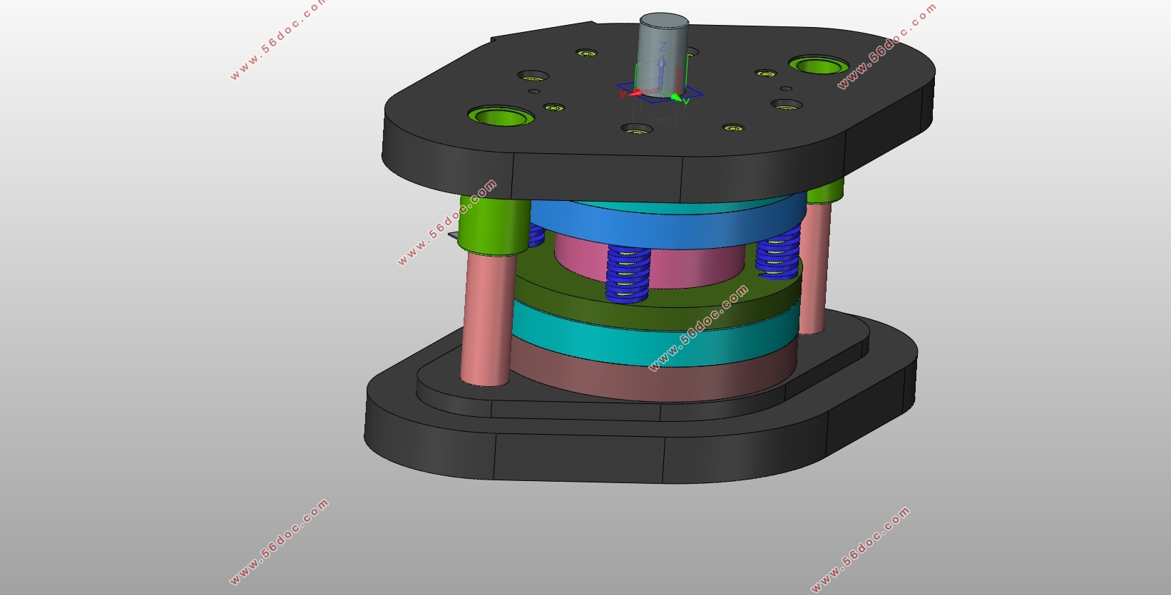
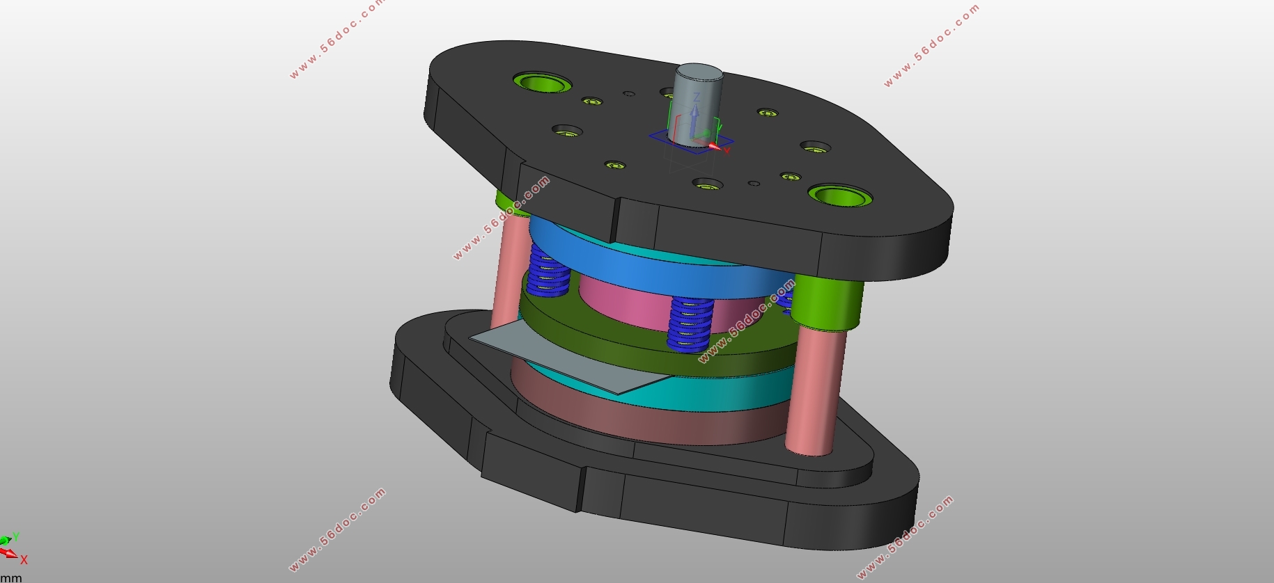
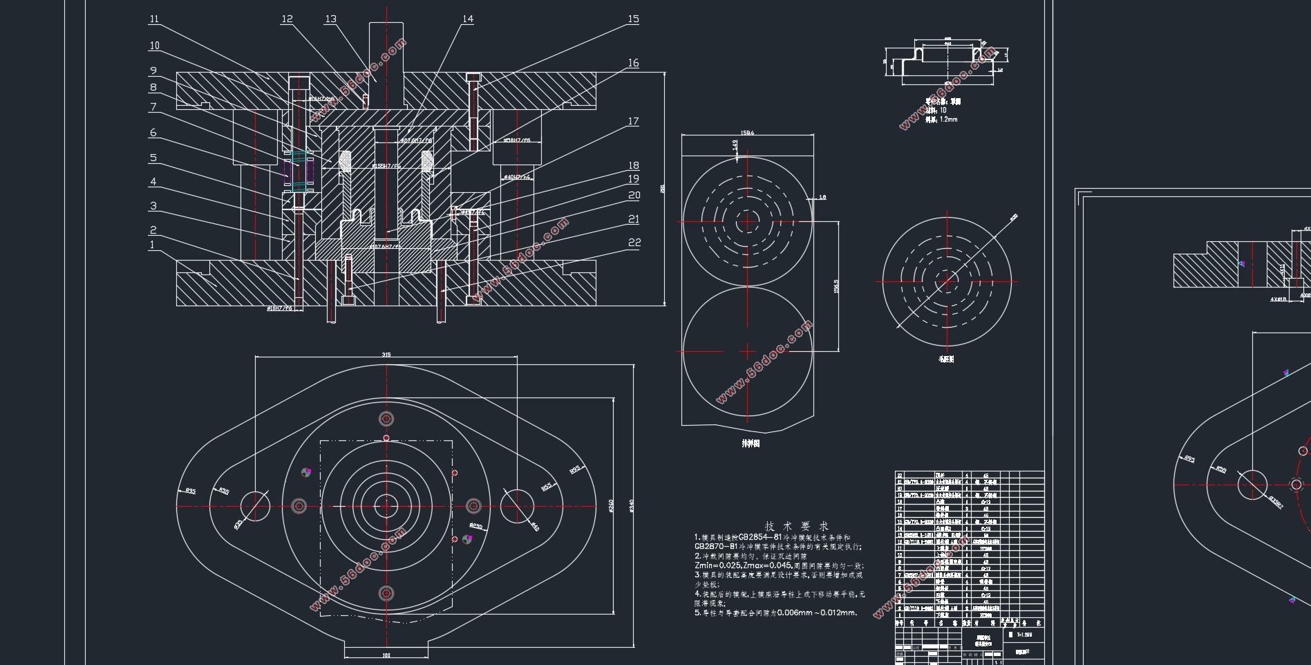
本文主要从生产的实际出发,结合自己对于罩圈零件的理解进行设计。通过对冲压件的实际建模,分析出各道工序,通过多种方案之间的比较,本文采用复合模具结构,模具中设置了落料、冲孔、拉伸,翻边等工序。并且对边落料拉伸零件的材料、尺寸、形状和精度进行冲压工艺分析,设计出合理的排样图。对模具设计中的重要的工序过程进行模具设计,设计了复合模具的主要结构,对于翻孔凹凸模具进行了结构分析和设计,对其结构尺寸进行了合理的分析计算,确定了其整体结构特征。本文通过合理的结构设计以及可靠的分析计算,使得设计的模具能够广泛的适用于较大零件的加工制造,同时能够适用于结构复杂的冲压零件,通过分析时间,采用了合理的结构设计,提高了产品的质量。
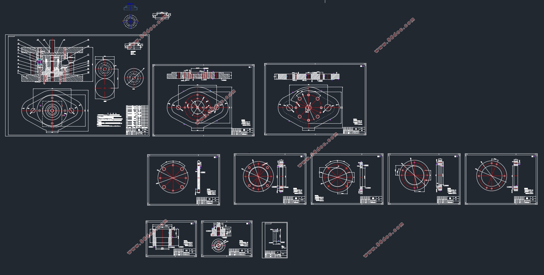
最终根据模具的工艺分析计算,对模具的零部件进行合理的设计和选用。在设计中对模具的总体结构进行设计,包括上下模座、导柱导套、垫板、固定板、导料板、卸料板等的设计与选用。通过对以上步骤的检验,确定工艺的完整性和可行性,在进行压力机的选用和模具材料的选择,最终可以完成整副模具的绘制。不仅考验了学生的融会贯通能力,也从中学习了新的设计思路和设计思想,了解了更多的零件模具的设计,开阔了视野。
关键词:罩圈;设计;模具 ;计算;绘图;校核
Abstract
This paper mainly from the actual production, combined with their understanding of the ring parts for the design. Through the actual modeling of stamping parts, analysis of each process, through the comparison of various programs, this paper adopts the compound die structure, die set up blanking, punching, stretching, flanging and other processes. The material, dimension, shape and precision of the part are analyzed, and the reasonable layout drawing is designed. The main structure of the compound die is designed, the structure of the flanging and concave-convex die is analyzed and designed, and the reasonable structure size is analyzed and calculated, the overall structural characteristics are determined. Through reasonable structure design and reliable analysis and calculation, the designed die can be widely applied to the processing and manufacturing of larger parts, and also can be applied to the stamping parts with complex structure, the reasonable structure design is adopted and the quality of the product is improved. Finally, according to the mold process analysis and calculation, the mold parts for reasonable design and selection. In the design of the overall structure of the mold design, including the upper and lower mold base, guide pillar bushing, backing plate, fixed plate, guide plate, discharge plate and so on. Through the inspection of the above steps, to determine the integrity and feasibility of the process, in the selection of press and die material selection, the final can complete the whole die drawing. Not only test the ability of students to understand, but also learn from the new design ideas and design ideas, understand more parts and mold design, broaden the vision.
Key words: Ring; design; mold; calculation; drawing; Check
零件冲压工艺分析
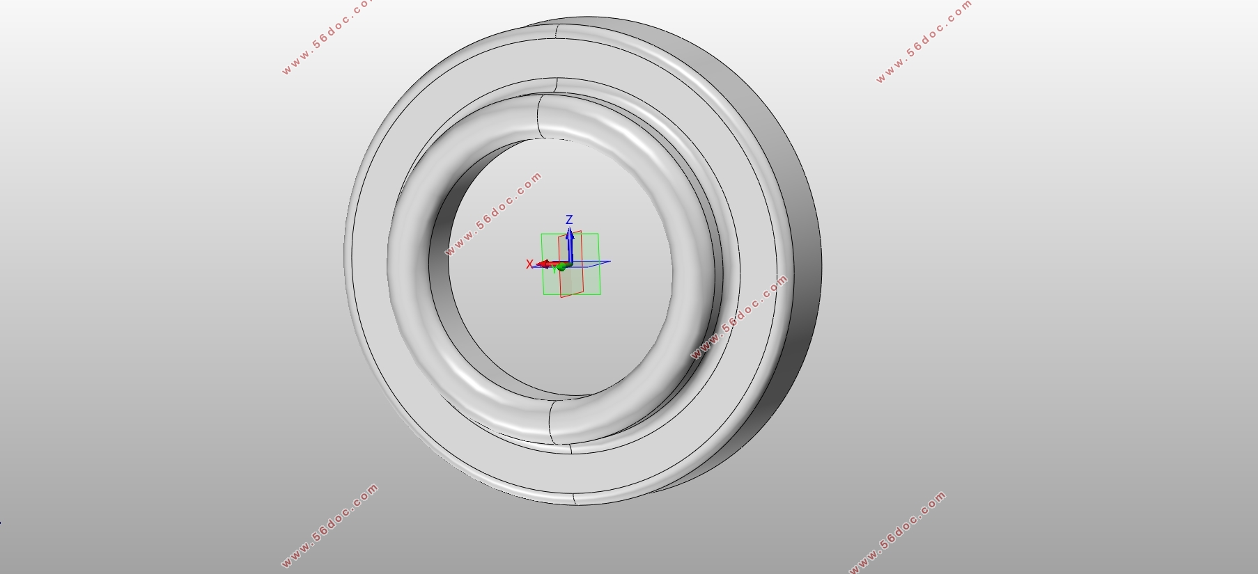
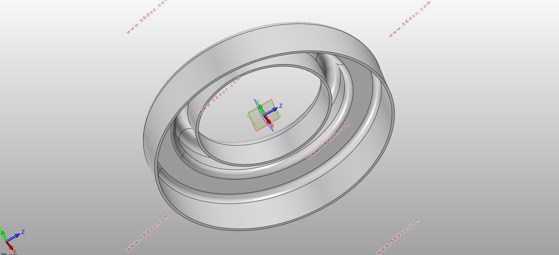
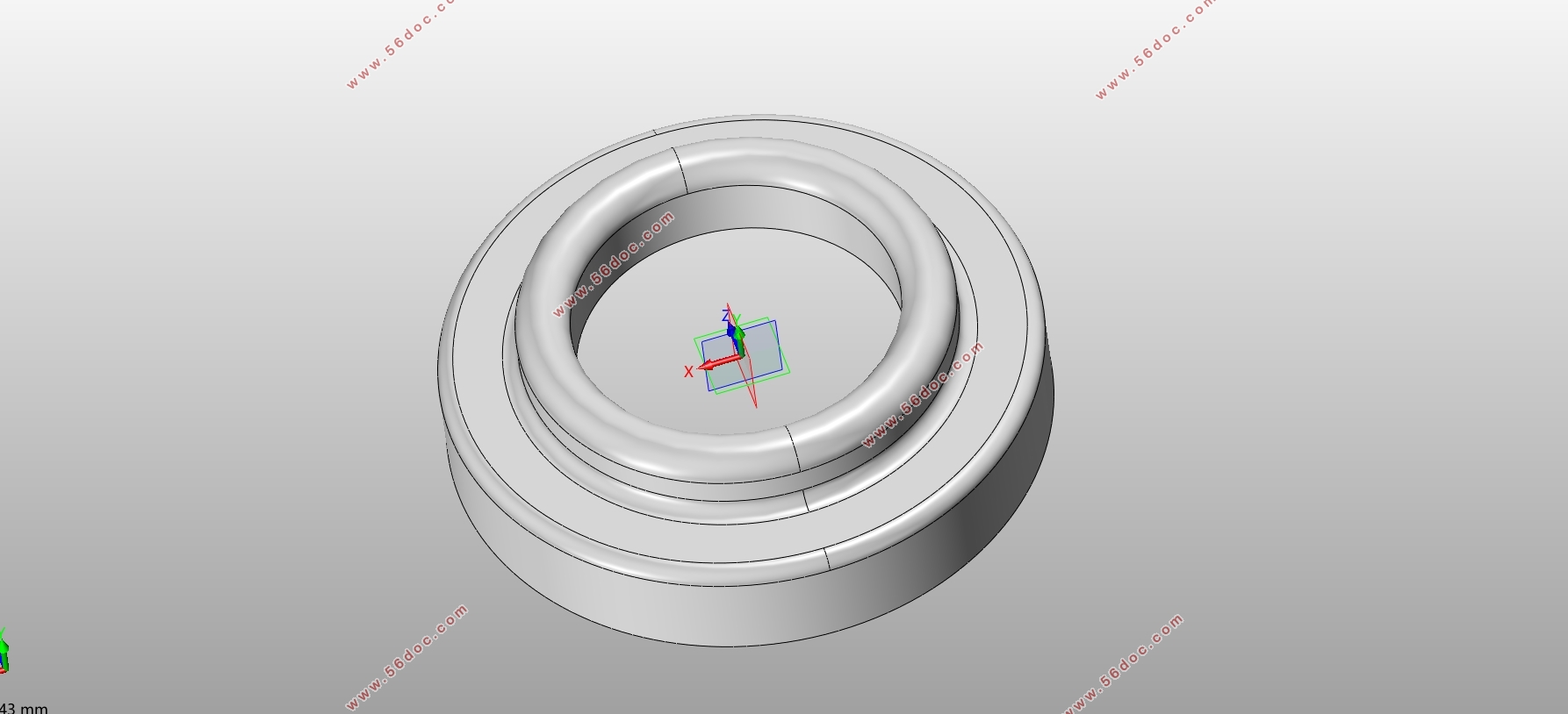
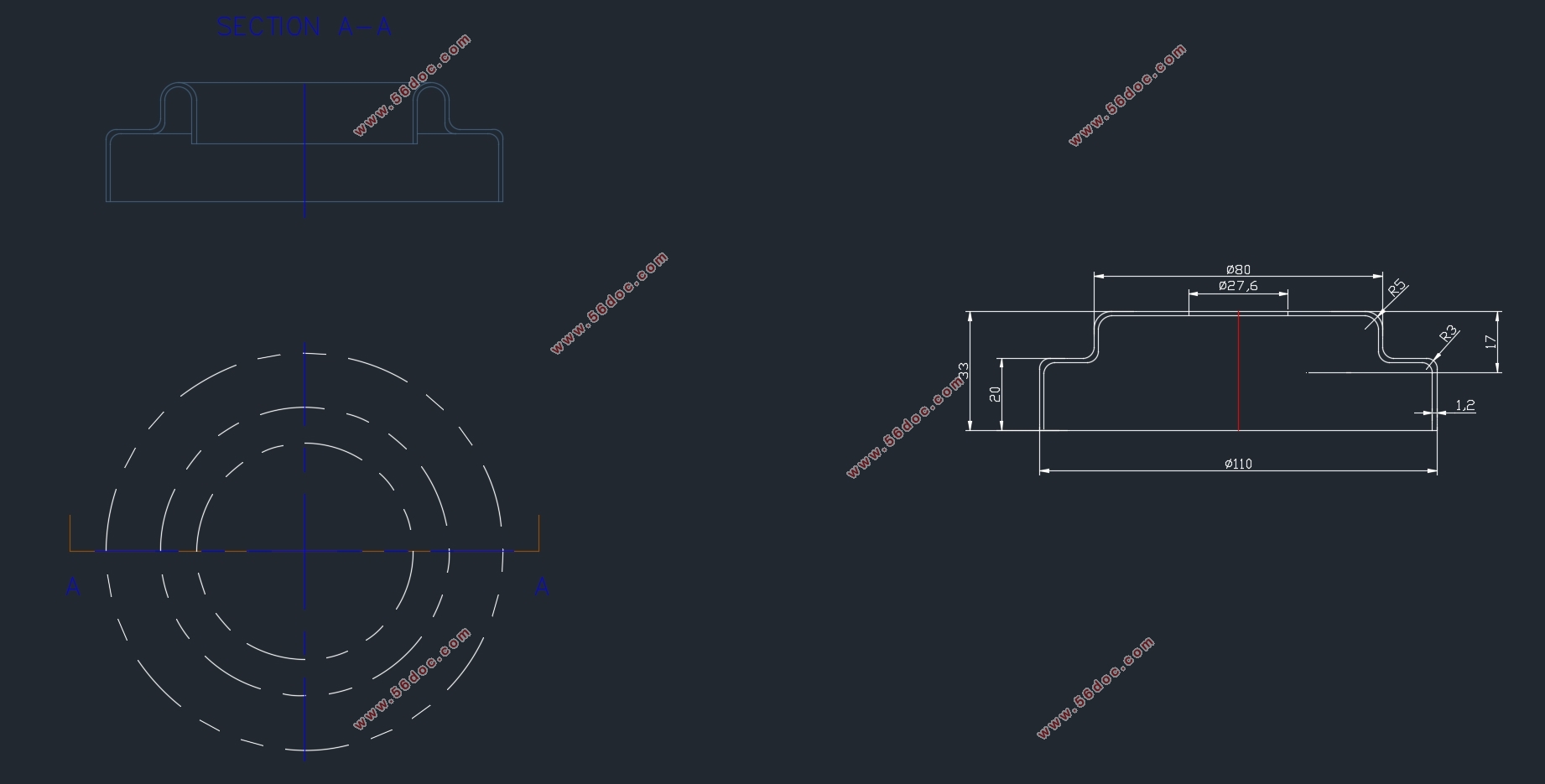
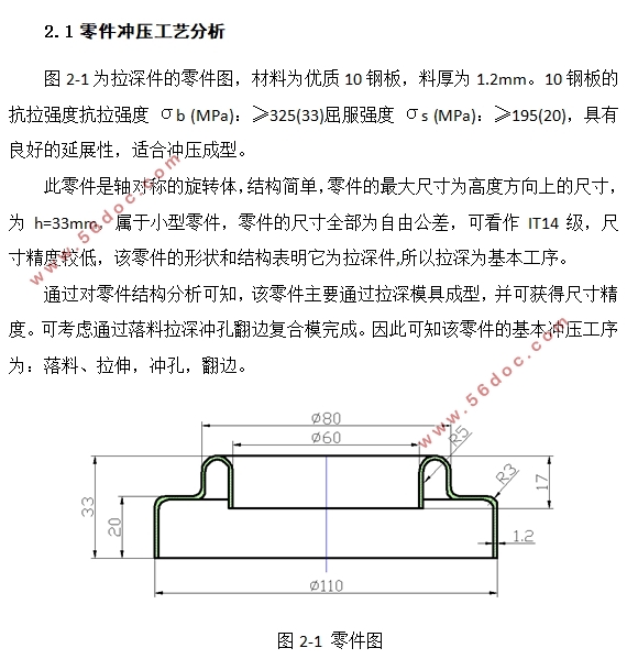
图2-1为拉深件的零件图,材料为优质10钢板,料厚为1.2mm。10钢板的抗拉强度抗拉强度 σb (MPa):≥325(33)屈服强度 σs (MPa):≥195(20),具有良好的延展性,适合冲压成型。
此零件是轴对称的旋转体,结构简单,零件的最大尺寸为高度方向上的尺寸,为h=33mm,属于小型零件,零件的尺寸全部为自由公差,可看作IT14级,尺寸精度较低,该零件的形状和结构表明它为拉深件,所以拉深为基本工序。
通过对零件结构分析可知,该零件主要通过拉深模具成型,并可获得尺寸精度。可考虑通过落料拉深冲孔翻边复合模完成。因此可知该零件的基本冲压工序为:落料、拉伸,冲孔,翻边。
目录
摘 要 1
Abstract 2
目录 3
第一章 绪论 5
1.1引 言 5
1.2模具工业在国民经济中的作用 5
1.3模具发展概况 6
1.4 课题研究的主要内容和意义 7
第二章 有凸缘筒形件拉深工艺分析 9
2.1 零件冲压工艺分析 9
2.2 拟定工艺方案 9
2.2.1 计算毛坯尺寸 9
2.2.2 罩圈的拉深次数分析 11
2.2.4拟定工艺方案 13
第三章 主要工艺参数的计算 14
3. 1 排样方案的确定 14
3. 2 搭边的选取 15
3.3送料步距、条料宽度及板料间距计算 16
3.4 压力中心的计算 18
3.5计算各工序压力、选用压力机 18
3.5.1 计算工艺力 18
3.5.2 卸料力、推件力、和顶件力的计算 20
3.5.3模具总冲压力计算 21
3.5.3 初选压力机 21
3.6 计算凸、凹模刃口尺寸和公差 22
第四章 落料拉伸冲孔翻边复合模设计 26
4.1凸模和凹模设计 26
4.1.1 凸模 26
4.1.2 凹模 27
4.1.3 凸凹模 28
4.2卸料和压边方法设计 29
4.3定位位零件的设计 30
4.4柱、导套的选用 31
4.5模架及其零件的设计 32
4.6模具工作过程 33
4.8 模柄 33
4.9 卸料装置 33
4.9 其他支撑与固定零件 34
4.9.1凸模固定板 34
4.9.2垫板 34
4.9.3 紧固件 34
总结 35
致谢 36
参考文献 37
|


