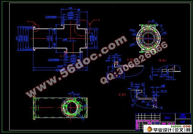
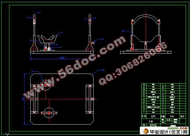
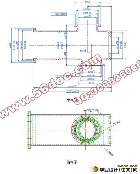
法兰管件的数控加工(选题审批表,任务书,开题报告,过程检查表,毕业论文11000字,cad图纸2张)
摘要:
加工中心由于备有刀库并能自动更换刀具,使得工件在一次装夹中可以完成多工序的加工。加工中心一般不需要人为干预,当机床开始执行程序后,它将一直运行到程序结束。加工中心还赋予了专业化车间一些诸多优点,如:降低机床的故障率,提高生产效率,提高加工精度,削减废料量,缩短检验时间,降低刀具成本,改善库存量等。由于加工中心的众多优势,所以它深受全球制造企业的青睐。
法兰,又叫法兰盘或突缘,使管子与管子相互连接的零件,连接于管端。法兰上有孔眼,可穿螺栓,使两法兰紧连。法兰间用衬垫密封。法兰管件指带有法兰的管件。它可由浇铸而成,也可由螺纹连接或焊接构成。法兰联接由一对法兰、一个垫片及若干个螺栓螺母组成。
关键词:加工中心、法兰管件
ABSTRACT
CNC Machining Center with a knife as a result of the Treasury and can automatically replace the tool, the workpiece in a fixture to be completed in multi-processing processes. Processing centers do not require human intervention, when the machine after the beginning of the implementation process, it will have to run to the end of the process. CNC Machining Center workshop also gives some of the many advantages of specialization, such as: machine tools to reduce the failure rate, increase productivity, improve processing accuracy, reduce the waste volume and shorten the test time, lower tool costs and improve inventory and so on. Processing center as a result of the many advantages it by the favor of global manufacturing enterprises.
Flange, also known as process flange or edge, so that the pipe and pipe parts connected to each other, connected to pipe end. There are hole flange can be bolted to wear so that the two flange abuts. With liner sealing flange between. Flanged pipe fittings refers to the pipe with a flange. It can be cast from, but also may pose a thread connection or welding. Flange connected by a flange, a gasket and nut composed of a number of bolts.
Key words: CNC machining center、langed pipe fittings
.主要任务
我们独立完成一项给定的设计任务,编写符合要求的设计说明书,并正确绘制有关图表。
(1) 知识要求
绘制零件二维CAD图
(2) 明确加工要求
确定机械加工流程,确定加工所需要的机床,所用的刀具等其他要求
(3) 明确数控加工内容 确定数控加工工序,确定各工序尺寸
(4) 确定数控加工所用的机床,选择加工所用的刀具包括(刀杆、刀片)、刀柄、接杆等
(5) 根据相关的尺寸选择相应的切削用量
(6) 在以上基础上编写出相应的数控加工工序卡片、数控加工刀具卡片
(7) 根据相应的工件编制相应数控加工程序
(8) 最后完成相应的毕业设计说明书的编写,说明书的内容要有各参数作为依据
1. 2 毕业设计的任务和要求
毕业设计包括二维CAD软件进行零件造型、参数的选择、工艺设计和机床夹具设计。
毕业设计包括零件的工艺分析、数控机床的选用、零件工艺方案设计,包括加工余量、切削用量、机床夹具的选择等内容。最终完成零件的数控加工工序卡片,数控刀具卡片等。
目录
一、绪论………………………………………………………………………4
1. 1 目的…………………………………………………………………4
1. 2 毕业设计的任务和要求……………………………………………5
二、机械加工工艺过程分析…………………………………………………6
2.1 工件图样分析………………………………………………………7
2.2 定位基准选择………………………………………………………8
2.3 工艺方案拟定………………………………………………………9
2. 4 加工设备选择………………………………………………………10
三、数控加工工序分析………………………………………………………11
3. 1 加工顺序(工步顺序)……………………………………………11
3. 2 装夹方案和夹具的选择……………………………………………13
3. 3 刀具的选择…………………………………………………………14
3. 4 切削用量和工序尺寸的选择………………………………………15
四、数控加工程序……………………………………………………………16
五、数控加工过程……………………………………………………………33
5. 1 工件安装步骤和要点………………………………………………33
5. 2 刀具尺寸的输入……………………………………………………33
5. 3 找基准………………………………………………………………33
5. 4 工件立体图…………………………………………………………34
六、结论………………………………………………………………………35
七、致谢………………………………………………………………………37
八、参考文献…………………………………………………………………38
附表1数控加工工序卡………………………………………………………39
附表2数控加工工序卡………………………………………………………40
附表3数控加工工序卡………………………………………………………41
附表4数控加工刀具卡………………………………………………………42
附表5数控加工刀具卡………………………………………………………43
|
