基于PLC的PH自动控制加液机设计
来源:56doc.com 资料编号:5D22351 资料等级:★★★★★ %E8%B5%84%E6%96%99%E7%BC%96%E5%8F%B7%EF%BC%9A5D22351
资料以网页介绍的为准,下载后不会有水印.资料仅供学习参考之用. 密 保 惠 帮助
资料介绍
基于PLC的PH自动控制加液机设计(任务书,开题报告,外文翻译,论文说明书10000字)
摘要
pH值是工业生产中重要的参数,它广泛存在于石油化工、生物制药及废水处理等诸多领域。pH值的控制品质直接影响到产品的质量、排放指标的达标及企业的经济效益等,但pH值的控制问题一直是关心和研究的话题,并且从来没有停止过。
随着近几年来国家对环境问题的关心,企业越来越重视对pH值得控制。因此本人基于s7-200SMART PLC并使用西门子触摸屏作为实时监控设备,设计了一套以实现pH值在线监控测量与自动加液调整机构于一体的自动化控制设备。
本设计涉及硬件和软件两方面。硬件方面,完成西门子公司的S7-200 SMART系列的PLC与PC机和执行元件步进电机及pH检测元件的连线。软件方面分为四块:第一块是pH值采集程序;第二块是pH值显示部分程序;第三块是PID控制及驱动部分程序;第四块是报警及通讯部分程序。软件部分比较复杂。
关键词:PLC pH值 采集
PLC automatic control of PH Dosing Based Design
Abstract
The pH is an important parameter in industrial production, it is widely present in many fields of petrochemical, pharmaceutical and biological wastewater treatment. The pH control quality directly affects the quality and effectiveness of product standards and emission targets, such as businesses, but to control the pH of the problem has been the topic of concern and research, and never stopped.
With the country in recent years, concern for environmental issues, business is worth more attention to pH control. So I based s7-200SMART PLC and Siemens touch screen as the real-time monitoring equipment, designed to achieve a set of on-line monitoring of pH measurement and automatic adjustment mechanism was in one of the automatic control equipment.
The design involves both hardware and software. Hardware, complete wiring Siemens S7-200 SMART series PLC and PC and stepper motor actuators and pH sensing element. Software is divided into four areas: the first one is the pH value acquisition program; second block is the pH of the display part of the program; and the third block is a PID control and drive part of the program; the fourth block is part of the program the alarm and communications. Software part is more complicated.
Key word: PLC ;pH value;Collection


目 录
摘要 I
Abstract II
第一章绪论 1
1.1 课题背景 1
1.2 系统整体目标 2
1.3 PLC以及通讯协议选择 3
1.3.1 PLC选择 3
1.3.2 通信协议选择 3
第二章元器件及软件开发工具介绍 5
2.1 S7-200 SMART CPU 5
2.2模拟量扩展模块 9
2.3 S7-200 SMART的程序编写 10
2.4 STEP 7-MicroWIN SMART简介 13
2.4.1STEP 7-MicroWIN SMART软件的安装要求 13
2.4.2 STEP 7-MicroWIN SMART窗口元素和区域 13
IMATIC SMART LINE屏简介 18
2.6 SIMATIC Win软件简介 18
2.7伺服器及步进电机介绍 18
2.7.1伺服器的作用 18
2.7.2步进电机的定义 18
2.7.3步进电机的工作原理 18
2.7.4步进电机的主要参数 18
2.8 pH控制器 19
2.8.1pH控制器的定义 19
2.8.2 pH控制器的简介 19
2.8.3 pH控制器的主要参数 19
第三章硬件设计 22
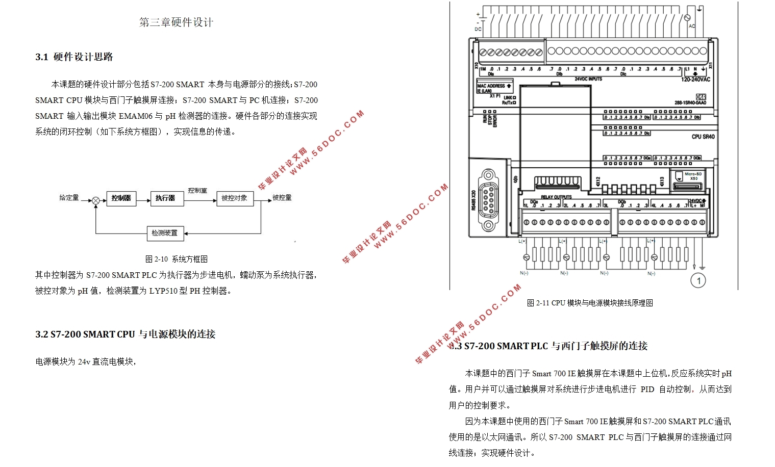
3.1硬件设计思路 22
3.2S7-200 SMART CPU与电源模块的连接 22
3.3S7-200 SMART PLC与西门子触摸屏的连接 22
3.4S7-200 SMART模块与PC机的连接 25
3.5 S7-200 SMART模块与pH检测元件的连接 26
3.6 步进电机驱动器与PLC的连接 27
3.7步进电机驱动器与步进电机的连接 25
第四章软件设计 28
4.1 程序设计思想 28
4.2 PLC程序部分 28
4.2.1 pH值采集部分程序的设计 28
4.2.2 pH值显示部分程序的设计 29
4.2.3PID控制程序设计 35
4.2.4驱动部分程序的设计 39
4.2.5通讯部分程序的设计 39
第五章调试及成果展示 40
5.1调试 43
5.2展示 43
结语 50
参考文献 51
致谢 52
|


