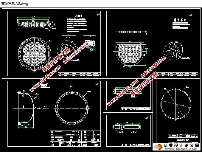
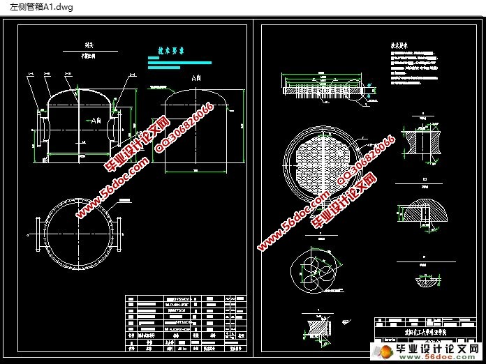
流量250t/h双管程固定管板式换热器(含CAD图)(设计说明书14000字,CAD图纸8张)
摘要
这篇论文主要介绍的是换热器机械计算等相关的设计过程。换热器是将热流体的部分热量传递给冷流体的设备。换热器在石油、化工等许多工业生产中占有重要地位,其中固定管板式换热器最为常见。固定管板式换热器是由两端管板和壳体构成的,由于其结构简单,因此运用比较广泛。
换热器在石油、化工、轻工、制药、能源等工业生产中,常常用作把低温流体加热或者把高温流体冷却,把液体汽化成蒸汽或者把蒸汽冷凝成液体。换热器既可是一种单元设备,如加热器、冷却器和凝汽器等;也可是某一工艺设备的组成部分,如氨合成塔内的换热器。换热器是化工生产中重要的单元设备,根据统计,热交换器的吨位约占整个工艺设备的20%有的甚至高达30%,占有非常重要的地位。列管式换热器又叫做管壳式换热器,是一种通用的标准换热器。它具有结构简单、坚固耐用、造价低廉、用材广泛、清洗方便、适应性强等优点,在化工生产中应用最为广泛。冷热流体分别流经管程、壳程,由于温度不同,热膨胀程度有所不同,当温度大于50℃时,导致设备弯曲、变形,甚至破裂,此时应考虑热膨胀因数,并设法加以补偿,根据热补偿的方式不同可分为固定管板式换热器、浮头式换热器、U型管式换热器、填料函式换热器、釜式换热器等 。20世纪20年代出现板式换热器,并在食品工业中使用。与代管制成,结构紧凑,传热效果好,从而逐渐发展成为各种形式的板式换热器。 30年代初,瑞典首次成螺旋板式换热器。那么英国的法律体系营造钎焊铜及铜合金由冷却飞机发动机的板翅式换热器制造。 30年代后期,瑞典创造了纸浆厂第一壳式换热器。在此期间,为了解决强腐蚀性介质的散热问题,人们的新材料开始关注到热交换器。管壳式换热器是现如今应用最广的换热设备,它具有较高的可靠性和简单容易操作性,特别是在较高参数的工作条件下,管壳式换热器更显示了它独有的长处。在换热器的热流分析中,引入计算机技术,对换热器中介质的复杂流动过程进行定量的模拟仿真。目前基于计算机技术的热流分析已经用于自然对流、剥离流、振动流和湍流热传导等的直接模拟仿真,以及对辐射传热、多相流和稠液流的机理仿真模拟等方面。综上所述,随着强化传热理论的研究,加强管壳式换热器的改进,将高效传热管与壳程强化传热的支撑结构相结合是今后换热器发展的一个重要方向。综合考虑各方面因素,生产高质量、低成本的换热器,在推动生产发展的同时,也会获得较高的经济效益 。
本文引用一部分相关参考文献以及各项技术标准,对固定管板式换热器的结构、强度等进行了系统性的阐述。本设计采用单壳程、双管程,通过合理的计算,确定它的各项工艺参数,并正确的选择材料,确保它的安全运行,提高设备的生产效率,降低设备的制造成本。最终完成图纸的设计任务。
关键词: 换热器; 管板; 壳体; 管箱; 封头
Abstract
This writing paper mainly introduces the calculation of heat exchange is mechanical related design process. Heat exchange is parts of the thermal fluid heat transfer to the cold fluid equipment. Heat exchange in the petroleum, chemical industry and many other industrial productions occupies on important position, the fixed tube pate heat exchange is the most common. It is composed of tube sheet and shell on both ends, due to its simple structure, so use more widely.
Heat ex changer in the oil industry, chemical industry, light industry, pharmaceuticals, energy and other industrial production, often used as a low temperature fluid heating or cooling high temperature fluid, the liquid into steam or the steam condensed liquid. Heat ex changer can be either a unit equipment, such as heater, cooler and condenser,etc. It can also be a part of the industrial equipment, such as ammonia synthetic tower’s heat ex changer. Heat ex changer is important in the chemical production unit equipment, according to statistics, the tonnage of heat ex changer accounted for about 20% of the entire process equipment, some even as high as 30%, occupies very important position.Shell and tube heat ex changer, also known as tube heat ex changer heat ex changer is a kind of universal standards. It has simple structure, strong and durable, low cost, convenient material widely, cleaning, and the advantages of strong adaptability, the most widely used in chemical production.Cold and hot fluid flows through the tube side and shell side respectively, owing to the different temperature, thermal expansion degree is different, when the temperature is greater than 50 ℃, the lead to equipment bending and deformation, even burst, thermal expansion factor should be considered at this time, and try to compensate, according to the different thermal compensation can be divided into fixed tube plate heat ex changer, floating head heat ex changer, the U tube heat ex changer, the stuffing box type heat ex changer, heat ex changer, etc. In the 1920 s a plate heat ex changer, and used in the food industry. With escrow, compact structure, good heat transfer effect, and gradually developed into various forms of plate heat ex changer. The early 30 s, Swedish into spiral plate heat ex changer for the first time. Britain's legal system construction brazing of copper and copper alloy made by the aircraft engine cooling fin heat ex changer. Late 30 s, the Swedish created the pulp mill first heat ex changer. In the meantime, in order to solve the problem of strong corrosive medium heat, people begin to pay close attention to the new material to heat ex changer. Tube and shell heat ex changer is now the most widely used heat exchange equipment, it has high reliability and easy probability, especially under the condition of high parameter of work, tube and shell heat ex changer and more shows its unique advantages. In the heat ex changer heat flow analysis, the introduction of computer technology, the process of the complex flow heat ex changer mediation qualitative to quantitative simulation. The heat flow analysis based on computer technology has been used in natural convection, stripping flow, vibration direct simulation of flow and turbulence heat conduction, and radiation heat transfer, the mechanism of multipurpose flow and viscous flow simulation, etc. To sum up, along with the research achievements on enhancement of heat transfer theory, strengthen the improvement of tube and shell heat ex changer, would transmit the efficient heat pipe heat transfer enhancement and the shell side of the combined support structure is an important direction of the development of the heat ex changer in the future. Considering the factors, the production of high quality and low cost of heat ex changer, in promoting the development of production at the same time, also can obtain higher economic benefits.
Part of this paper reference relevant references and technical standard, the structure of fixed tube plate heat exchange, such as strength are systematically described. Through the calculation of aggregate, determine its various process parameters, and the right choice of materials, to ensure its safe operation, improve equipment production efficiency, and reduce the manufacturing cost of the equipment. It is the final drawings of design tasks.
Key words: Heat exchange; tube sheet; shell; tube box; head
目 录
第一章 绪论 1
1.1 引言 1
1.2 换热器的结构 2
1.3 换热器的类型 3
1.4 换热器强化传热 4
1.5 换热器的发展前景 5
第二章 换热器的工业设计 7
2.1 工艺计算 7
2.1.1 设计任务与条件 7
2.1.2 换热器类型的确定 7
2.1.3 确定物性参数 7
2.1.4 传热量与煤油流量计算 8
2.1.5 有效平均温差计算 8
2.2 计算尺寸 9
2.2.1 管程换热系数计算 9
2.2.2 结构的初步设计 10
2.2.3 壳程换热系数计算 10
2.2.4 传热系数计算 11
2.2.5 管壁温度计算 11
第三章 换热器零部件的工业结构设计 12
3.1 换热管材料及规格的选择和根数的确定 12
3.2 布管方式的选择 12
3.3 筒体内径的确定 12
3.4 筒体壁厚的确定 13
3.5 封头形式的确定 13
3.6 管箱短节壁厚计算 14
3.7 容器法兰的选择 14
第四章 换热器的强度设计及校核 15
4.1 筒体的计算 15
4.2 对于延长部分兼作法兰的管板的计算 16
4.3 假定管板厚度的计算 18
4.4 值的计算 19
4.5 法兰厚度的计算 20
4.6 法兰力矩的组合 20
4.6.1 只有壳程设计压力PS,而管程设计压力Pt=0,不计膨胀节变形差(即r=0) 20
4.6.2 只有壳程设计压力,而管程设计压力Pt=0,并且计入膨胀变形差 22
4.6.3 只有管程设计压力Pt,而壳程设计压力PS=0,不计膨胀节变形差 23
4.6.4 只有管程设计压力Pt,而壳程设计压力PS=0,同时计入膨胀变形差 24
4.6.5 由管板计算厚度来确定管板的实际厚度 25
4.7 是否安装膨胀节的确定 25
4.8 折流板尺寸的确定 26
4.9 各管控接管及其法兰的确定 26
4.10 设备法兰的选择 28
4.11 拉杆和定距管的确定 29
4.12 开孔补强计算 30
4.13 筒体管箱耐压试验的应力校核的计算 31
4.14 支座的选择及应力校核 32
4.14.1 支座的选择 32
4.14.2 鞍座的应力校核 32
参考文献 35
致谢 36
|


